|
|
|
Categories
|
|
Information
|
|
Featured Product
|
|
|
 |
|
|
There are currently no product reviews.
 ;
Very good reproduction (copy) of original manual. Didn't have a parts list, but schematic was completely labeled with parts. Complete instructions on how to adjust mechanical functions of the 8-track deck. Well worth having and at a very reasonable cost.
;
It's a full manual. All the parts are in there. I haven't found the problem yett, but I am working on it; hope I can rebuild the part myself. To make it more secure and unbreakable this time. Because the part has failed several times before and costs a lot to let it be repaired.
Thanks so much for this rich illustrated and parted manual.
;
I downloaded the document. The manual was complete, well scanned and everything was legible. I could zoom in see what I needed to know. There's not much more that you can ask.
;
It was complete service manual with all needed service informations. Thanks.
 ;
El manual esta muy detallado, los numeros de partes y los esquemas de despiece son correctísimos y muy claros, tanto para los técnicos experimentados como para los novatos.
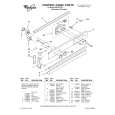
1-4-5. V Board
Removal 1. Remove the base assembly. (Refer to Section 1-3-1.) 2. Remove the rear cover and rear panel. (Refer to Section 1-3-3.) 3. Remove the two hooks of the rear panel, then remove the V board. 4. Disconnect the harness from the connector (CN30) on the V board.
1-4-6. Lamp Power Supply Board
Removal 1. Remove the cabinet. (Refer to Section 1-3.) 2. Remove the C board. (Refer to steps 3 to 6 of Section 1-4-1.) 3. Remove the lamp assembly. (Refer to steps 2 and 3 of Section 1-5-2.) 4. Remove the three screws and disconnect the harness from the connector (CN14) on the F board, then remove the lamp power supply unit. 5. Remove the two screws, then remove the lamp house. 6. Loosen the two screws, then remove the connector.
BTP 3 x 12 Lamp power supply unit
Rear panel
Hooks
CN30
BTP 3 x 12 Lamp house Screws
Harness
V board
Connector
Installation 5. Install the V board in the reverse order of steps 3 and 4. 6. Assemble this unit in the reverse order of steps 1 and 2.
Harness
CN14
F board
1-8
VPL-HS60/HS51A
|
|
|
> |
|