|
|
|
Categories
|
|
Information
|
|
Featured Product
|
|
|
 |
|
|
There are currently no product reviews.
 ;
We received the manual in a timely manner and it was exactly what we were expecting. Excellent replacement for original Service Manual.
All schematics are very legible. We are really satisfied.
;
We received the manual in a timely manner and it was exactly what we were expecting. Excellent replacement for original Service Manual.
All schematics are very legible. We are really satisfied.
;
We received the manual in a timely manner and it was exactly what we were expecting. Excellent replacement for original Service Manual.
All schematics are very legible. We are really satisfied.
;
We received the manual in a timely manner and it was exactly what we were expecting. Excellent replacement for original Service Manual.
All schematics are very legible. We are really satisfied.
;
We received the manual in a timely manner and it was exactly what we were expecting. Excellent replacement for original Service Manual.
All schematics are very legible. We are really satisfied.
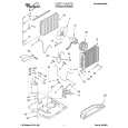
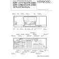
KRF-V7771D/V8881D/VR-2080/2090
CIRCUIT DESCRIPTION
1. The back up item and initialization condition
1-1 Back up
� POWER ON/OFF � VOLUME LEVEL � AUDIO INPUT � SELECTOR � VIDEO INPUT � SELECTOR � SPEAKER A � SPEAKER B � CD2/TAPE2 MONITOR � TONE � LOUDNESS � DISPLAY MODE � RDS DISPLAY MODE � DIMMER � SURROUND MODE � DSP MODE � ROOM SIZE � WALL TYPE � EFFECT LEVEL � MIDNIGHT MODE � DISTANCE : OFF : -66dB : TUNER : VIDEO1 : ON : OFF : TAPE2 OFF : OFF : OFF : DEVICE+DGTL/ANLG : FREQUENCY : DIMMER 1 (LIGHTEST) : STEREO : ARENA : Med : Med :3 : OFF : FL/FR : 10ft : C : 10ft : RS/LS : 5ft : SW : 10ft : LARGE : NORMAL � SURROUND SP. � SUB WOOFER � SW Re-Mix � INPUT LEVEL : NORMAL/WIRED : ON : OFF : 0dB
� CH. LEVEL : 0dB � TONE BASS : 0dB � TONE TREBLE : 0dB � TUNING MODE : AUTO � PRESET MEMORY : TEST MEMORY FREQUENCY (Same value with KR-V999D/1090VR) � LAST BAND � FM LAST FREQUENCY � AM LAST FREQUENCY � LAST P. ch � PTY SELECT MODE � PTY SEARCH MODE � TP SEARCH MODE � RDS DISPLAY MODE : FM : 87.5MHz : 531kHz (CH. SP 9kHz) : 530kHz (CH. SP 10kHz) : [- -ch] : OFF : OFF : OFF : FREQUENCY MODE
1-2 The initial setting
While pressing POWER key, plug the AC power cord into an AC outlet (K,P type) or turn on the AC POWER switch.
� FRONT SP. � CENTER SP.
2. Condition by the destination or model
TYPE K1 1700 K2 1610 K4 1700 RBDS E1 E3 RDS Q1 RDS M BAND FM AM FM AM Reception frequency 87.5MHz~108.0MHz 530kHz~1700kHz 87.5MHz~108.0MHz 530kHz~1610kHz Channel space 100kHz 10kHz 100kHz 10kHz IF +10.7MHz +450kHz +10.7MHz +450kHz PLL standard frequency 25kHz 10kHz 25kHz 10kHz
77
(0 : Pull down, 1 : Pull up) DSW3 0 0 1 0 0
76
Diode sw DSW2 75 DSW1 0 0 0 0 1 0 0 1 1 0
74 DSW0
0 1 0 1 1
FM 87.5MHz~108.0MHz 100kHz +10.7MHz 25kHz AM 530kHz~1700kHz 10kHz +450kHz 10kHz FM 87.5MHz~108.0MHz 50kHz +10.7MHz 25kHz AM 531kHz~1602kHz 9kHz +450kHz 9kHz FM 87.5MHz~108.0MHz 50kHz +10.7MHz 25kHz AM 531kHz~1602kHz 9kHz +450kHz 9kHz FM L 65.0MHz~74.0MHz 10kHz +10.7MHz 5kHz FM H 87.5MHz~108.0MHz 50kHz +10.7MHz 5kHz AM 531kHz~1602kHz 9kHz +450kHz 9kHz K2/E1 is switched with only the setting of DSW1 (X11 : S601). (DSW1 = 0 : K2 type, 1 : E1 type)
1 0
0 0
1 X
1 1
3. TEST MODE
[setting method] While pressing INPUT SELECTOR key, plug the AC power cord into an AC outlet (K, P type) or turn on the AC POWER switch. When a set is set up in test mode condition a set becomes the following condition. Automatic POWER ON. All indicator tube (FL) and
CLIP INDICATOR LED are lighted. The other LED are flashed. A backup at the thing except ON/OFF of POWER is initialized. [cancel method] The power supply is turned off.
9
|
|
|
> |
|