|
|
|
Categories
|
|
Information
|
|
Featured Product
|
|
|
 |
|
|
There are currently no product reviews.
 ;
Fully functional usable service manual. Considering the age of the manual and device quality was better than expected
 ;
Thank you very much, I've been very happy to find this manual on "Owner Manual". It's a perfect copy and it has been really useful for my work!
;
It took about 24-hours after my payment before I was able to get to the download. Apparently, payment processing is not 100% automated. That is no big deal, just be aware of that going in.
After I got to it, it was in good shape, easy to read, etc. Not some cheap FAX copy looking thing.
Also, this site was the cheapest I found. Another Plus!
;
Good price, very legible manual, exactly what I needed -- but had to wait a day to actually get the download of the manual. Would have preferred to download it immediately after payment rather than waiting for someone to "process" my order. I was surprised that I had to wait that long.
;
As the only source for this manual it rather rank quite high since it is well scanned and perfectly readable.
KRF-X9995D/X9995D-S/VR-5700/5900
DISASSEMBLY FOR REPAIR
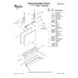
How to Remove the Front Panel and the Motor Assy
1. How to Remove the Front Panel
1. Remove the screws (1X3) on top of the panel. 2. Remove the screws (2X9) located at the the bottom of the panel. 3. Disconnect the cable (3) and connectors (4,5) on the X13 A/6. 4. Disconnect the connector (6) on the X07 A/5. 5. Cut the tie band (7X7) as shown in the figure. 6. Remove the screw (8X1) on the X25 F/11. 7. Disconnect the connector (9 ) on the X25 G/11.(Except K/P type) 8. Remove the hooks (0X2) on the sub panel. 9. Remove the front panel in the direction of arrow.
X07 (A/5)
KRF-X9995D/VR-5900
11 x4
9
MOTOR AC CONNECTOR (EXCEPT K/P)
6
CN8
1 x3
8
7 x7
X25 (G/11) X25 (F/11)
2. How to Remove the Motor Assy
1. The motor assy can be separated by removing screws (-X4).
2 x5 10 x2
HOOK X13 (A/6)
3
CN3 CN1 CN2
4
5
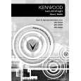
Disassembling the Rear Panel and How to Replace the Power Transistor
1. Disconnect the CN10 on the X07 C/5. 2. Remove all of screws (1X61) and digital caps (2X8) on the rear panel. (The number of screws and caps are vary according to the models). 3. Disconnect the cable CN16 (3) on the X13 A/6. 4. Disconnect the flexible cables CN101(4) on the X25 C/11, CN102 (5) and * CN103 (6)on the X25 B/11. * (K/P type only). 5. Remove the rear panel in the direction of arrow. 6. Remove the screw (7), then remove the X25 B/11.
2 x8
X25 C/11
2 x4
3
X13 A/6
CN16 CN102
5
X25 B/11
CN103
4
CN101
6
CN10
X07 C/5
7
X25 B/11
1 x61
9
X05
8
CN1
11
10 x2
10 x2
FRAME(B)
10 x2
7. To remove the tuner unit, disconnect the CN1 (8) and remove a screw (9). 8. Remove the screws (0X9) on the frames (A/B/C), push rivet (-) and PC support (=x2)on the X11 A/2.
FRAME(A) FRAME(C)
10 x2
10
X11 A/2
12 x2 12
3
|
|
|
> |
|