|
|
|
Categories
|
|
Information
|
|
Featured Product
|
|
|
 |
|
|
There are currently no product reviews.
 ;
Good quality service manual.It has helped me to fix my FV1800,particularly for replacing the dial cord.The scheme is on A3 format and very readable.Thank.Olivier.
;
This manual is complete and very readable.It was a great help for my two ICF5800L.The first one had the dial cord broken,and without the service manual it is impossible to replace it.Thank.Olivier.
 ;
This is a top quality manual. You couldn't get better if you had the original and scanned it yourself. Best price on the net as well. Diagrams are clear and complete, text is sharp and easy to read. Granted you don't get the manual the second you click pay, but the few hours you have to wait for it to be available for download isn't a problem at all. This is a very reliable company.
Very VERY pleased with the product, and will buy others. Thanks!
;
In a word AWESOME.
I never expected the quality and abundant content that I got with this manual. Everything you'd ever want to know from a service perspective is found in this manual, along with... as a bonus, operating instructions on how to use the unit. WOW. Very impressed with the quality of the manual. You won't be disappointed if you're looking for the EVS900 service manual.
;
I thank Owen-Manuals.com for the wonderful service rendered to me, and this manual which I purchased helped me a lot in servicing my Denon System, which was lying in a dead state.
Thanks Owner-Manual.com
KRF-V7070D/V8070D/X9070D/VR-7060/7070/7080
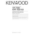
EXTERNAL VIEW / ADJUSTMENT
EXTERNAL VIEW
Knob (K29-8107-02) Panel * (A60-) Knob ass'y * (K29-) Front glass * (B10-) Knob ass'y * (K29-) Knob * (K29-)
VOLUME CONTROL POWER
STANDBY
THX SPEAKER EQ
ON/STANDBY
DOLBY DIGITAL DTS CS II DSP STEREO INPUT MODE DIMMER
ACTIVE EQ THX
A SPEAKERS B
SPEAKER EQ ACTIVE EQ
DOWN MUTE DVD/6CH CD/DVD PHONO TUNER SOUND TONE
PHONES
UP
MULTI CONTROL SETUP
LISTEN MODE AV AUX S VIDEO VIDEO L-AUDIO-R
VIDEO 1
VIDEO 2
VIDEO 3
MD/TAPE BAND AUTO MEMORY
Phone jack (E11-0271-05)
Knob (K29-8111-02)
Knob * (K29-)
Pin jack (E63-1251-05) Cylindrical receptacle (E56-0033-05)
Illust. is VR-7060. * Refer to parts list on page 29 .
ADJUSTMENT
No. ITEM INPUT OUTPUT SETTINGS SETTINGS SPEAKER : A CN11, FL ch. CN10, FR ch. CN14, SL ch. CN13, SR ch. CN12, C ch. CN15, SW ch. X09(A/5) RECEIVER SETTINGS ALIGNMENT POINTS VR1(FL) VR2(FR) VR3(SL) VR4(SR) VR5(CENTER) VR6(SUB WOOFER) X09(A/5) ALIGN FOR FIG.
AUDIO SECTION
<1>
IDLE CURRENT
-
(FRONT 2ch MODE) Volume: Minimum
Adjust every potentiometer 10 minutes later after turned the power on.
Idling Current Adjustment All power amplifier stage need idling current adjustment after the installation of TRAIT transistor. 1. Connect a voltmeter to CN11 with the correct polarity as indicated by the PCB silk print. 2. Adjust the preset, VR1 to get 8.8mV (Idling current = 20mA) at the voltmeter reading. 3. Repeat step 1 and 2 for all other channels.
3
|
|
|
> |
|