|
|
|
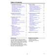
Categories
|
|
Information
|
|
Featured Product
|
|
|
 |
|
|
There are currently no product reviews.
 ;
Quick response.
Good quality.
Not large price of documents.
Thanks.
Dzięki.
;
All ok:
Good quality.
Quick response.
Not large price of documents.
Thanks
;
The manual was complete and extremely helpful in both diagnosing the problem I was having as well as fixing it. Excellent quality. I will getting additional manuals in the future.
;
Exactly the JVC service manual and schematics that I was looking for - delivered just hours after order. Will do business again!
;
This is a fantastic site, ad I have been a returning satisfied cusumer!
Thanx for a great sevice!
1-A. Preliminary/Final Checking and Alignment of Tape Path
Purpose: To make sure that the tape path is well stabilized. Symptom of Misalignment: If the tape path is unstable, the tape will be damaged. Note: Do not use an Alignment Tape for this procedure. If the unit is not correctly aligned, the tape may be damaged. 1. Playback a blank cassette tape and check to see that the tape runs without creasing at Guide Rollers [2] and [3], and at points A and B on the lead surface. (Refer to Fig. M3 and M4.) 2. If creasing is apparent, align the height of the guide rollers by turning the top of Guide Rollers [2] and [3] with a Guide Roller Adj. Screwdriver. (Refer to Fig. M3 and M5.)
Guide Roller [2] Guide Roller [3]
3. Check to see that the tape runs without creasing at Take-up Guide Post [4] or without snaking between Guide Roller [3] and AC Head. (Fig. M3 and M5) 4. If creasing or snaking is apparent, adjust the Tilt Adj. Screw of the AC Head. (Fig. M6)
Azimuth Adj. Screw
AC Head X-Value Adj. Screwdriver
Tilt Adj. Screw
Fig. M6
1-B. X Value Alignment
Purpose: To align the Horizontal Position of the Audio/Control/ Erase Head. Symptom of Misalignment: If the Horizontal Position of the Audio/Control/Erase Head is not properly aligned, maximum envelope cannot be obtained at the Neutral position of the Tracking Control Circuit. Fig. M3 1. Connect the oscilloscope to TP301 (C-PB) and TP501 (CTL) on the Main CBA. Use TP502 (RFSW) as a trigger. 2. Playback the Gray Scale of the Alignment Tape (FL6NS8) and confirm that the PB FM signal is present. 3. Set the Tracking Control Circuit to the center position by pressing CH UP button then � PLAY � button on the unit. (Refer to note on bottom of page 2-3-4.)
ACE Head
A
B Take-up Guide Post [4]
Lead Surface of Cylinder
Tape
Fig. M4
4. Use the X-Value Adj. Screwdriver so that the PB FM signal at TP301 (C-PB) is maximum. (Fig. M6) 5. Press CH UP button on the unit until the CTL waveform has shifted by approx. +2msec. Make sure that the envelope is simply attenuated (shrinks in height) during this process so that you will know the envelope has been at its peak.
Correct
Guide Roller Tape
Incorrect
Take-up Guide Post Tape
Fig. M5
2-3-3
U27PMAPC
|
|
|
> |
|