|
There are currently no product reviews.
 ;
A very good complete archive, i am very satisfied for document.
 ;
The Service Manual received was helpful. The electronic information is exactly what I needed.
;
The Manual was perfect.
The deliverie was perfect.
Thanks
;
Found website easy to use and manual very clear. First class service
;
The quality is quite good and clear. Nothing of the informations inside is lost during the digitalizing process
MODELS: VS-45609 / VS-50609 / VS-55609 / VS-60609 / VS-60719 / VS-70709
CRT REPLACEMENT
1. Removal of the CRT
Caution! High voltage should be completely discharged prior to CRT removal. Since The CRTs receive high voltage from the CR Block, discharge by shorting the open end of the respective high voltage cable to chassis ground.
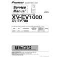
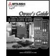
Note: Refer to figures 1-1 through 2-2 when performing steps 1 through 4. 1. 2. 3. 4. 5. 6. Remove the Speaker Grille, Front Board, and Screen Assy. Remove the Back Board. Remove the Anode Lead Wire from the CR Block. Remove the PCB-CRT. Remove 4 hex-screws "a" retaining the Optical Unit. [Figure 5-1] Remove 4 screws "b" retaining the Lens. Note: DO NOT loosen the RED screws. Doing so will break the seal between the C-Element and the # 6 Lens, causing leakage of the CRT Coolant. 7. Remove 4 screws "c" retaining the CRT. [Figure 5-2] 8. Remove the Deflection Yoke from the neck of the CRT. [Figure 5-7]
Figure 5-1
Figure 5-2
Note: The 4 spring-loaded screws shown in Fig 5-2 and labeled as "DO NOT REMOVE", should not be loosened under any circumstance. Doing so will break the seal between the CRT and the CRT-Spacer, causing leakage of the CRT Coolant.
Page 14
|