|
|
|
Categories
|
|
Information
|
|
Featured Product
|
|
|
 |
|
|
There are currently no product reviews.
 ;
Excellent manual. In addition to the information I needed was a complete description of both electronic and mechanical devices.
Excellent site.
Thank you very much.
 ;
very good and complete manual , it is in english and german is perfect for repair.
;
This manual is complete and of high quality. I am very pleased with the purchase.
;
Another excellent buy! A fully readable PDF archive. Good prints!!
;
It is wonderful done!!! a great job in scanning the manual. Superior quality in all the electric scheme. Very understandable and net!!! Thank you!
VS-DT68V
Attaching the pickup unit (See Figs. 6 to 8.)
[Reference] Refer to the explanation of "Removing the pickup unit" on the preceding page. 1. Attach the P.S. spring and rack to the pickup unit. (See Fig.6.) 2. Insert the C.D shaft into the pickup unit. (See Fig.6.) 3. Engage the section f of the pickup unit with the traverse mechanism assembly first, and set the both ends of the C.D shaft in the grooves g and h. (See Fig.7.) 4. After making sure that the section j of the rack is meshed correctly with the middle gear, attach the C.D shaft using the two screws F. (See Fig.8.)
Groove g
Section f
Groove h
Fig.7
Section j
F
Rack
Fig.8
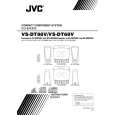
Removing the traverse mechanism board (See Fig. 9.)
Remove the CD servo board and video board. Remove the traverse mechanism assembly. 1. From the back side of the traverse mechanism assembly, disconnect the spindle motor wires and feed motor wires that are soldered on the traverse mechanism board. 2. Remove the two screws J attaching the traverse mechanism board.
J
Traverse mechanism assembly
Spindle motor Black Red Red Traverse mechanism board
K
Feed motor
J
Removing the feed motor (See Fig. 9.)
Remove the CD servo board and video board. Remove the traverse mechanism assembly. 1. From the back side of the traverse mechanism assembly, disconnect the feed motor wires that are soldered on the traverse mechanism board. 2. Remove the two screws K attaching the feed motor.
Fig.9
1-13
 $4.99 VS-DT68V JVC
Owner's Manual Complete owner's manual in digital format. The manual will be available for download as PDF file aft…
|
|
|
> |
|