|
|
|
Categories
|
|
Information
|
|
Featured Product
|
|
|
 |
|
|
There are currently no product reviews.
 ;
This is the 2nd time I download manuals from this website and I can say it's what I was expecting. It contains schematic, layout (decent quality), short description, parts and dissasembly instructions. I recomend it for anyone who wants to repair/modify this device.
;
Very useful Service Manual! With it I was able to identify the damaged pots in my old amplifier, purchase the adequate replacements and make myself the repair.
I have again my old amplifier, still a very good one that I will keep for as many years as I can!
Thanks to Owner Manuals!
;
Good price for the manual and easy to locate on the site and download. Plus, just like the original. Thanks a lot.
;
Genuine Service Manual. Link was available in less then an hour or so. Service Manual contains assembly, PCB layout, complete circuit diagram, Components list etc
;
Great and very well scanned Service Manual, also very fast download - Recomended !
5
6
7
8
A
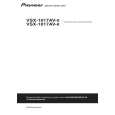
IC952 (Pin 14)
Step 6: DIR
Check that the SPDIF signal is output. Check that changes by pulling out and inserting the digital input lines. IC601 (Pin 1) No Replace IC952. Can No Check the DIGITAL INPUT Assy, observe the digital signal and parts and patterns in the path. ? (0 V � 4 V) Yes IC601 (Pin 5) IN2 (OPT: CD-R/TAPE/MD) IN1 (OPT: TV/SAT)
A
Do convert 3 V into 5 V for pin 6 input? Yes IC952 (Pin 13)
Do convert 3 V into 5 V for pin 7 input? Yes To Step 5
No
Replace IC952.
Can No Check the DIGITAL INPUT Assy, observe the digital signal and parts and patterns in the path. ? (0 V � 4 V) Yes IC601 (Pin 44) IN3 (COAX: DVD/LD) No Check the parts and patterns in the path. (1.65 V center, amplitude more than 0.2 Vp-p) IN4 (COAX: CD)
B
Step 5: X'tal
IC802 (Pin 2)
Can observe the digital signal ? Yes No Replace IC802 or X801.
Is there a 24.576 MHz output? Yes IC802 (Pin 7)
IC601 (Pin 42) Can observe the digital signal ? Yes
C
No
Check the parts and patterns in the path.
(1.65 V center, amplitude more than 0.2 Vp-p) Front IN (OPT: VIDEO2)
Is there a 24.576 MHz output? Yes IC802 (Pin 5)
No Check the path to pin 45 of IC801. Replace IC802. IC601 (Pin 7)
Can observe the No Check the FRONT IN Assy, and digital signal parts and patterns in the path. ? (0 V � 4 V) No Check the path to pin 30 of IC601. Replace IC802. Yes Check that the data and clock signals are output.
D
Is there a 24.576 MHz output? Yes
IC601 (Pin 27) To Step 6 Is there a master clock output? Yes
MCKO2 (Master clock) Is the voltage of PDN IC601-pin 31 5 V?
No
No Check the other assy. (surrounding of the microcomputer) No Replace IC601.
(0 V � 3.3 V)
E
IC601 (Pin 24)
LRCK (LR clock)
Is there a LR clock output? Yes
No Replace IC601. (0 V � 3.3 V)
B
F
VSX-1017AV-K
5 6 7 8
33
|
|
|
> |
|