|
|
|
Categories
|
|
Information
|
|
Featured Product
|
|
|
 |
|
|
There are currently no product reviews.
 ;
I am only search for 5 Minute, by it in 5 Minutes to and get ist in few ours! Best i found in the Internet and my Amplifer is repaired as well! Thank you
 ;
Readable text and good copy. Very much needed if you wish to do some repairs on this fine old unit.
;
Fint forløb med levering af manualen. Kvaliteten af skanningen betegnes som middel
;
I found the manual to be clear concise and complete. It was of immense assistance when removing the unit as the unit was over 22 years old and the wiring diagram was unobtainable from the manufacturer. The exploded drawings were clear as were the instructions and labels.
;
I will highly recommend this seller. They are honest, accurate, fast and responsible.
5
6
7
8
A
IC952 (Pin 14)
Step 6: DIR
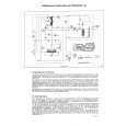
Check that the SPDIF signal is output. Check that changes by pulling out and inserting the digital input lines. IC601 (Pin 1) No Replace IC952. Can No Check the DIGITAL INPUT Assy, observe the digital signal and parts and patterns in the path. ? (0 V � 4 V) Yes IC601 (Pin 5) IN2 (OPT: CD-R/TAPE/MD) IN1 (OPT: TV/SAT)
A
Do convert 3 V into 5 V for pin 6 input? Yes IC952 (Pin 13)
Do convert 3 V into 5 V for pin 7 input? Yes To Step 5
No
Replace IC952.
Can No Check the DIGITAL INPUT Assy, observe the digital signal and parts and patterns in the path. ? (0 V � 4 V) Yes IC601 (Pin 44) IN3 (COAX: DVD/LD) No Check the parts and patterns in the path. (1.65 V center, amplitude more than 0.2 Vp-p) IN4 (COAX: CD)
B
Step 5: X'tal
IC802 (Pin 2)
Can observe the digital signal ? Yes No Replace IC802 or X801.
Is there a 24.576 MHz output? Yes IC802 (Pin 7)
IC601 (Pin 42) Can observe the digital signal ? Yes
C
No
Check the parts and patterns in the path.
(1.65 V center, amplitude more than 0.2 Vp-p) Front IN (OPT: VIDEO2)
Is there a 24.576 MHz output? Yes IC802 (Pin 5)
No Check the path to pin 45 of IC801. Replace IC802. IC601 (Pin 7)
Can observe the No Check the FRONT IN Assy, and digital signal parts and patterns in the path. ? (0 V � 4 V) No Check the path to pin 30 of IC601. Replace IC802. Yes Check that the data and clock signals are output.
D
Is there a 24.576 MHz output? Yes
IC601 (Pin 27) To Step 6 Is there a master clock output? Yes
MCKO2 (Master clock) Is the voltage of PDN IC601-pin 31 5 V?
No
No Check the other assy. (surrounding of the microcomputer) No Replace IC601.
(0 V � 3.3 V)
E
IC601 (Pin 24)
LRCK (LR clock)
Is there a LR clock output? Yes
No Replace IC601. (0 V � 3.3 V)
B
F
VSX-1017AV-K
5 6 7 8
33
|
|
|
> |
|