|
|
|
Categories
|
|
Information
|
|
Featured Product
|
|
|
 |
|
|
There are currently no product reviews.
 ;
I found this service manual to be complete in every detail except for troubleshooting charts. It would be helpful if it had a set of troubleshooting charts; however it is a very good manual otherwise and for the price it is very well worth it.
 ;
Complete manual included schematics layouts and alignment procedure, clear to read and magnify, extremely pleased with manual and owner manual . com's service
;
perfect, i am very satisfait for the réception of the sansui r-5l service manual, thank you very much
;
Thank you, this is a rare document. Few others have it, but they charge way more for a download.
Great deal (even if you have to wait a few hours to get it).
;
The purchased manual is an high quality scan of the original Philips paper-based Service Manual. I am very satisfied!
5
6
7
8
A
IC952 (Pin 14)
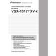
Step 6: DIR
Check that the SPDIF signal is output. Check that changes by pulling out and inserting the digital input lines. IC601 (Pin 1) No Replace IC952. Can No Check the DIGITAL INPUT Assy, observe the digital signal and parts and patterns in the path. ? (0 V � 4 V) Yes IC601 (Pin 5) IN2 (OPT: CD-R/TAPE/MD) IN1 (OPT: TV/SAT)
A
Do convert 3 V into 5 V for pin 6 input? Yes IC952 (Pin 13)
Do convert 3 V into 5 V for pin 7 input? Yes To Step 5
No
Replace IC952.
Can No Check the DIGITAL INPUT Assy, observe the digital signal and parts and patterns in the path. ? (0 V � 4 V) Yes IC601 (Pin 44) IN3 (COAX: DVD/LD) No Check the parts and patterns in the path. (1.65 V center, amplitude more than 0.2 Vp-p) IN4 (COAX: CD)
B
Step 5: X'tal
IC802 (Pin 2)
Can observe the digital signal ? Yes No Replace IC802 or X801.
Is there a 24.576 MHz output? Yes IC802 (Pin 7)
IC601 (Pin 42) Can observe the digital signal ? Yes
C
No
Check the parts and patterns in the path.
(1.65 V center, amplitude more than 0.2 Vp-p) Front IN (OPT: VIDEO2)
Is there a 24.576 MHz output? Yes IC802 (Pin 5)
No Check the path to pin 45 of IC801. Replace IC802. IC601 (Pin 7)
Can observe the No Check the FRONT IN Assy, and digital signal parts and patterns in the path. ? (0 V � 4 V) No Check the path to pin 30 of IC601. Replace IC802. Yes Check that the data and clock signals are output.
D
Is there a 24.576 MHz output? Yes
IC601 (Pin 27) To Step 6 Is there a master clock output? Yes
MCKO2 (Master clock) Is the voltage of PDN IC601-pin 31 5 V?
No
No Check the other assy. (surrounding of the microcomputer) No Replace IC601.
(0 V � 3.3 V)
E
IC601 (Pin 24)
LRCK (LR clock)
Is there a LR clock output? Yes
No Replace IC601. (0 V � 3.3 V)
B
F
VSX-1017AV-K
5 6 7 8
33
|
|
|
> |
|