|
|
|
Categories
|
|
Information
|
|
Featured Product
|
|
|
 |
|
|
There are currently no product reviews.
 ;
I PURHASED THIS PRODUCT BECAUSE I WAS HAVING PROBLEMS WITH MY CDR20 HARMAN KARDON RECORDER. WHICH I PURCHASED NEW 12 YEARS AGO. AFTER REVIEWING THE MANUAL, I WAS ABLE TO ADJUST THE TENSIONER IN THE SYSTEM. WORKS LIKE A CHAMP!.
SAVED ME AT LEAST 100.00 WHICH WAS WHAT A SERVICE REPAIR STATION WANTED. GREAT MANUAL EASY TO READ. SPECIALLY AFTER I PRINTED THE PAGES WHICH DEALT WITH MY RECORDER. THANKS A LOT!!!!!!!!
 ;
You can fully trust on this one!
All the schematics are very crear an in one piece per page
;
I have never bought a service manual which is as competely readable as this althogh it was a scanned pdf. Thank you for this succesful manual also cheaper than other sites.
;
Thanks for a very good and readable servicemanual. Just what I needed as a "dinosaur technician". I really recommmend this site and will come back.
Åsbjörn
;
The manual I purchased was just what I needed. I was glad to find a site where I can find so many manuals on a wide variety of products.
5
6
7
8
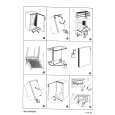
2. Diagnosis
1 POWER AMP Assy
A
1 2 3 4 5
Remove the Rear Panel. Remove the MAIN Assy (equipped with HDMI&DVC Assy and DSP&USB Assy) and the AUDIO IN Assy from the INTERFACE Assy. Discharge C5721 and C5722. (See the "discharge procedures.") Remove the two screws that fix the Regulators attached to the Chassis. Remove the two Push Rivets and the two screws that fix the POWER AMP Assy. Regulator
9
Remove the Locking Card Spacer from the Chassis using Cutting Pliers.
B
Locking Card Spacer (for fixing the Assy)
9 10 11 12 4 13
Cutting Pliers
Remove the four screws that fix the Heat Sink V5S. Cut the Binder. Remove the four screws that fix the Power Transformer. Place a high insulating material under the Power Transformer to raise it. Raise the block and diagnose the POWER AMP Assy B side.
C
Push Rivet
POWER AMP Assy
DIODE Assy
6
D
POWER AMP Assy
5
Caution: Fix the DIODE Assy to the Rear Panel with Tape so that it will not come closer to other Assy.
Tape DIODE Assy
E
6 7 8
Remove the two screws that fix the diode of the DIODE Assy. Reassembling the MAIN Assy (equipped with HDMI&DVC Assy and DSP&USB Assy) and the AUDIO IN Assy to the INTERFACE Assy. Reassembling the Rear Panel. (Keep a space for earth and about six to seven screws fixing places. Do not attach screws with the Chassis.)
Diagnosis
F
VSX-LX51
5 6 7 8
69
|
|
|
> |
|