|
|
|
Categories
|
|
Information
|
|
Featured Product
|
|
|
 |
|
|
There are currently no product reviews.
 ;
This is a good quality scan of the Operation & Maintenance (Service) Manual for the PAL version of this high-band broadcast umatic, BVU-800P
All schematics and lineup procedures appear to be included in this one manual AFAICT.
The file size is just over 113 MB which gives an idea of the quality and number of pages.
All of the schematics, which contain some fairly small print, are easily readable when you zoom into the page.
John Thompson, Newcastle Upon Tyne, England.
;
Good quality, all schematics of few of models. There is also short form of user manual and regulation manual.
;
Perfect copy of the service manual. you can enlarge every page, and it comes up
with all details.
;
It´s very very nice manual with all, what i need. Original in good quality. Very fast business. Very much thanks...
;
Purchased the manual that I was looking for at a great price and could download it easily.. Great service experience and for future purchases I plan to use the site.
Thank you very much
1
2
3
4
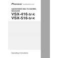
7.3.4.3 Troubleshooting Step 1: Connectors
A
CN701, CN702 Are the connectors securely inserted ? Yes
6
IC703 (pin 1), IC702 (pin 7)
3.3 V Reg. output / 1.8 V Reg. input Is IC703 abnormally hot? Yes No
No Insert the connectors securely.
Is the voltage 3.3 V ? Yes
No
Replace IC703.
To STEP 2 The output and GND may be short-circuited. Check the path between them.
Step 2: Power supply
B
7
IC762 (pins 37, 47) FLASH ROM
1
CN702 (pin 4) Is the voltage 5V? Yes
5 V input Is there any loose connection of CN702? Yes Is the voltage 3.3 V ? Yes Check the MOTHER Assy. No Check the parts and patterns in the path.
No
No
8
IC761 (pins 1,3,9,14,27,43,49) SDRAM
To STEP 1
2
C
IC703 (pin 3)
3.3 V Regulator IC input
Is the voltage 3.3 V ? Yes
No
Check the parts and patterns in the path.
Is the voltage 5V? Yes
No
Check the patterns in the path.
9
IC953 (pin 14) Is the voltage 3.3 V ? Yes
5-3 Converter
No
Check the parts and patterns in the path.
3
IC951 (pin 14)
3-5 Converter
D
Is the voltage 5V? Yes
No
Check the parts and patterns in the path.
10 IC701 (pins 16,33,64,76,112) USB Media control IC
Is the voltage 3.3 V ? Yes
No
Check the parts and patterns in the path.
4
IC771 (pin 5)
USB Power SW
Is the voltage 5V? Yes
E
No
Check the parts and patterns in the path.
11
IC702 (pin 1)
1.8 V Regulator output
5 IC7814 (pins 14, 15) DAC
Is the voltage 5V? Yes No Check the parts and patterns in the path.
Is the voltage 1.8 V ? Yes
No
Is IC702 abnormally hot? Yes
No
Replace IC702.
The output and GND may be short-circuited. Check the path between them.
A
F
116
1 2
VSX-516-K
3 4
|
|
|
> |
|