|
|
|
Categories
|
|
Information
|
|
Featured Product
|
|
|
 |
|
|
There are currently no product reviews.
 ;
Excellent printing quality.
A complete and very usefull service manual with all details.
GREAT SERVICE AT VERY LOW PRICE!
A+++++++++++++++++++++++++
;
Excellent printing quality.
A complete and very usefull service manual with all details.
GREAT SERVICE AT VERY LOW PRICE!
A+++++++++++++++++++++++++
;
Excellent printing quality.
A complete and very usefull service manual with all details.
GREAT SERVICE AT VERY LOW PRICE!
A+++++++++++++++++++++++++
;
Excellent printing quality.
A complete and very usefull service manual with all details.
GREAT SERVICE AT VERY LOW PRICE!
A+++++++++++++++++++++++++
;
Excellent printing quality.
A complete and very usefull service manual with all details.
GREAT SERVICE AT VERY LOW PRICE!
A+++++++++++++++++++++++++
1
2
3
4
A
A
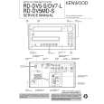
Step 6: DIR
Check that the SPDIF signal is output. Check that changes by pulling out and inserting the digital input lines. IC601 (Pin 1) No Replace IC952. Can No Check the DIGITAL INPUT Assy, observe the digital signal and parts and patterns in the path. ? (0 V � 4 V) Yes IC601 (Pin 5) IN2 (OPT: CD-R/TAPE/MD) IN1 (OPT: TV/SAT)
IC952 (Pin 14)
Do convert 3 V into 5 V for pin 6 input? Yes IC952 (Pin 13)
B
Do convert 3 V into 5 V for pin 7 input? Yes To Step 5
No Replace IC952. Can No Check the DIGITAL INPUT Assy, observe the digital signal and parts and patterns in the path. ? (0 V � 4 V) Yes IC601 (Pin 44) IN3 (COAX: DVD/LD) No Check the parts and patterns in the path. (1.65 V center, amplitude more than 0.2 Vp-p) IN4 (COAX: CD)
Step 5: X'tal
IC802 (Pin 2)
C
Can observe the digital signal ? Yes No Replace IC802 or X801.
Is there a 24.576 MHz output? Yes IC802 (Pin 7)
IC601 (Pin 42) Can observe the digital signal ? Yes
No
Check the parts and patterns in the path.
(1.65 V center, amplitude more than 0.2 Vp-p) Front IN (OPT: VIDEO2)
Is there a 24.576 MHz output? Yes
D
No Check the path to pin 45 of IC801. Replace IC802.
IC601 (Pin 7)
IC802 (Pin 5)
Can observe the No Check the FRONT IN Assy, and digital signal parts and patterns in the path. ? (0 V � 4 V) No Check the path to pin 30 of IC601. Replace IC802. Yes Check that the data and clock signals are output.
Is there a 24.576 MHz output? Yes
IC601 (Pin 27) To Step 6 Is there a master clock output?
E
MCKO2 (Master clock) Is the voltage of PDN IC601-pin 31 5 V?
No
No Check the other assy. (surrounding of the microcomputer) No Replace IC601.
(0 V � 3.3 V) Yes
IC601 (Pin 24)
LRCK (LR clock)
Is there a LR clock output? Yes
F
No Replace IC601. (0 V � 3.3 V)
B
72
1 2
VSX-517-K
3 4
|
|
|
> |
|