|
|
|
Categories
|
|
Information
|
|
Featured Product
|
|
|
 |
|
|
There are currently no product reviews.
 ;
I have this hi-fi system for a long time and I need to repair some things. Founding this manual will be very helpfull :)
 ;
It is pretty good. The schematics were covered all components, the manual also provide the parts list . It's useful for the trouble shooting.
;
Very fast service, best quality of the service manual and the schematics
;
This service manual of the old video cassette recorder VT-LC50EM is very good readable even the tiniest numbers (i.e. IC-pins). The circuits are very clear. Many details of the schematic are very good described but in GERMAN language. Many schematic details - but complete at all. Common background information of several details are enclosed and physical knowledge of the TFT liquid crystal display for example. The manual lacks PCB drawings. If you understand german I would recommend this manual for you.
;
Hi, this is a very clear manual, nice copy, not quite up to the standard of the very best available but better than many others. I think the price was especially fair for a hard to find manual and I would certainly use this manual seller again. Recommended.
1
2
3
4
A
A
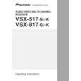
Step 6: DIR
Check that the SPDIF signal is output. Check that changes by pulling out and inserting the digital input lines. IC601 (Pin 1) No Replace IC952. Can No Check the DIGITAL INPUT Assy, observe the digital signal and parts and patterns in the path. ? (0 V � 4 V) Yes IC601 (Pin 5) IN2 (OPT: CD-R/TAPE/MD) IN1 (OPT: TV/SAT)
IC952 (Pin 14)
Do convert 3 V into 5 V for pin 6 input? Yes IC952 (Pin 13)
B
Do convert 3 V into 5 V for pin 7 input? Yes To Step 5
No Replace IC952. Can No Check the DIGITAL INPUT Assy, observe the digital signal and parts and patterns in the path. ? (0 V � 4 V) Yes IC601 (Pin 44) IN3 (COAX: DVD/LD) No Check the parts and patterns in the path. (1.65 V center, amplitude more than 0.2 Vp-p) IN4 (COAX: CD)
Step 5: X'tal
IC802 (Pin 2)
C
Can observe the digital signal ? Yes No Replace IC802 or X801.
Is there a 24.576 MHz output? Yes IC802 (Pin 7)
IC601 (Pin 42) Can observe the digital signal ? Yes
No
Check the parts and patterns in the path.
(1.65 V center, amplitude more than 0.2 Vp-p) Front IN (OPT: VIDEO2)
Is there a 24.576 MHz output? Yes
D
No Check the path to pin 45 of IC801. Replace IC802.
IC601 (Pin 7)
IC802 (Pin 5)
Can observe the No Check the FRONT IN Assy, and digital signal parts and patterns in the path. ? (0 V � 4 V) No Check the path to pin 30 of IC601. Replace IC802. Yes Check that the data and clock signals are output.
Is there a 24.576 MHz output? Yes
IC601 (Pin 27) To Step 6 Is there a master clock output?
E
MCKO2 (Master clock) Is the voltage of PDN IC601-pin 31 5 V?
No
No Check the other assy. (surrounding of the microcomputer) No Replace IC601.
(0 V � 3.3 V) Yes
IC601 (Pin 24)
LRCK (LR clock)
Is there a LR clock output? Yes
F
No Replace IC601. (0 V � 3.3 V)
B
72
1 2
VSX-517-K
3 4
|
|
|
> |
|