|
|
|
Categories
|
|
Information
|
|
Featured Product
|
|
|
 |
|
|
There are currently no product reviews.
 ;
Ordered service manuel for a hard to find plasma tv - your company made it easy to find and purchase - I will use you again
Thanks for your help
 ;
This is a high quality manual with clear schematic and components layout diagrams ; with service procedure included.
;
This service manual for the Kenwood KT-990D was reproduced really well ,is very legible and manual is complete.Combined with the low price paid,in the future,I will be checking Owner-Manuals.com any time I need a manual.
;
When I purchased this manual I had my doubts regarding the quality as the price was so reasonable as compared to other outlets.
The manual itself is of high standard the print is very clear as are the diagrams. Obviously with the diagrams one has to zoom in otherwise it is to small to be able to read.
Overall I am very pleased with the company who delivered as they said and with the manual they supplied.
I occasionally require a manual and now having registered with this company I shall order from them in the future.
;
I was at first dubious about payiong for downloaded manuals but having done so, I was extremely impressed with quality of the two manual I ordered, well worth the small price I paid.
I would highly recommend these to my friends.
1
2
3
4
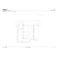
Step 6: DIR A
A
Check that the S/PDIF signal is output. Check that changes by pulling out and inserting the digital input lines. IC601 (pin 1) IN1 (OPT: TV/SAT)
IC952 (pin 14) Do convert 3 V into 5 V for pin 6 input? Yes IC952 (pin 13) Do convert 3 V into 5 V for pin 7 input? Yes To Step 5
No Replace IC952.
Can No Check the DIGITAL INPUT Assy, observe the digital signal and parts and patterns in the path. ? (0 V <-> 4 V) Yes IC601 (pin 5) IN2 (OPT: CD-R/TAPE/MD)
B
No
Replace IC952.
Can observe the No Check the DIGITAL INPUT Assy, digital signal and parts and patterns in the path. ? (0 V <-> 4 V) Yes IC601 (pin 44) Can observe the digital signal ? Yes IN3 (COAX: DVD/LD)
Step 5: X'tal
IC802 (pin 2)
C
No
Check the parts and patterns in the path.
(1.65 V center, amplitude more than 0.2 Vp-p) IN4 (COAX: CD)
Is there a 24.576 MHz output? Yes IC802 (pin 7)
No Replace IC802 or X801.
IC601 (pin 42)
Can observe the No Check the parts and patterns digital signal in the path. ? (1.65 V center, amplitude more than 0.2 Vp-p) Yes No Check the path to pin 45 of IC801. Replace IC802. IC601 (pin 27) Is there a master clock output? No Check the path to pin 30 of IC601. Replace IC802. MCKO2 (Master clock) Check that the data and clock signals are output.
Is there a 24.576 MHz output? Yes
D
IC802 (pin 5)
Is there a 24.576 MHz output? Yes To Step 6
Is the No voltage of PDN IC601-pin 31 5 V? (0 V <-> 3.3 V) Check the other assy. (surrounding of the Yes microcomputer) No No Replace IC601.
IC601 (pin 24)
LRCK (LR clock)
E
Is there a LR clock output? Yes
No Replace IC601. (0 V <-> 3.3 V)
B
F
20
1 2
VSX-518-K
3 4
|
|
|
> |
|