|
There are currently no product reviews.
 ;
Great scanned service manual
Usefull informations.
I will buy again!
Best Regards
;
The manual describes this product very good. It has the basic things to know and also a more detailed look. Very well made!
;
An excellent document to assist in the repair of my old personal tape player. It includes full circuit diagrams and physical layout drawings and full instructions on disassembly and fault finding.
Well worth the meagre price.
;
Very good conversation, Pretty fast Service, wood do it again,
Have paid by Paypal, so i got the Service Manual online after 15 Min.
Very helpfully.
Greeting from Germany,
Hans
;
Good-quality scans. Detailed description. I hope I can repair the machine.
1
2
3
4
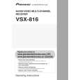
7.3.4.3 Troubleshooting Step 1: Connectors
A
CN701, CN702 Are the connectors securely inserted ? Yes
6
IC703 (pin 1), IC702 (pin 7)
3.3 V Reg. output / 1.8 V Reg. input Is IC703 abnormally hot? Yes No
No Insert the connectors securely.
Is the voltage 3.3 V ? Yes
No
Replace IC703.
To STEP 2 The output and GND may be short-circuited. Check the path between them.
Step 2: Power supply
B
7
IC762 (pins 37, 47) FLASH ROM
1
CN702 (pin 4) Is the voltage 5V? Yes
5 V input Is there any loose connection of CN702? Yes Is the voltage 3.3 V ? Yes Check the MOTHER Assy. No Check the parts and patterns in the path.
No
No
8
IC761 (pins 1,3,9,14,27,43,49) SDRAM
To STEP 1
2
C
IC703 (pin 3)
3.3 V Regulator IC input
Is the voltage 3.3 V ? Yes
No
Check the parts and patterns in the path.
Is the voltage 5V? Yes
No
Check the patterns in the path.
9
IC953 (pin 14) Is the voltage 3.3 V ? Yes
5-3 Converter
No
Check the parts and patterns in the path.
3
IC951 (pin 14)
3-5 Converter
D
Is the voltage 5V? Yes
No
Check the parts and patterns in the path.
10 IC701 (pins 16,33,64,76,112) USB Media control IC
Is the voltage 3.3 V ? Yes
No
Check the parts and patterns in the path.
4
IC771 (pin 5)
USB Power SW
Is the voltage 5V? Yes
E
No
Check the parts and patterns in the path.
11
IC702 (pin 1)
1.8 V Regulator output
5 IC7814 (pins 14, 15) DAC
Is the voltage 5V? Yes No Check the parts and patterns in the path.
Is the voltage 1.8 V ? Yes
No
Is IC702 abnormally hot? Yes
No
Replace IC702.
The output and GND may be short-circuited. Check the path between them.
A
F
134
1 2
VSX-816-K
3 4
|