|
|
|
Categories
|
|
Information
|
|
Featured Product
|
|
|
 |
|
|
There are currently no product reviews.
 ;
Excellent Service Manual and best price on the Internet. This Service Manual covers everything you could ever need including full circuit schematics, component layout diagrams, stripdown procedure and full parts list/breakdown. I needed this to carry out a modification to one of these headunits and this manual covered everything I needed. Fast delivery, processed within a few hours.
 ;
Thought I would never find a copy of the Technics SX-EN2 Service Manual until I found Owner-Manuals.com. Price was very fair and I received the download promptly. While a photocopy, it is quite readable and includes all the pertinent information and diagrams. Thank you Owner-Manuals!
;
I really like this manual and it's reliable.I found and bought easly.thank you.
;
Thank you very much. the Instruction corresponds to my expectations. Sent it in time. I don't regret that paid money.
;
Good quality. Quick service. I recommend to everyone.
1
2
3
4
C
A
R452 C414 SY IN
VCSDA
b-2
Is there a Y signal? Yes C420 SC IN No Diagnose between the BOARD TO BOARD Assy and S. VIDEO Assy.
d-1
Is there a same signal as VCSDA (0 to 3.3 V)? Yes R454 VCSCL No Check the Q451. If Q451 is failure, replace Q451.
b-3
B
d-2
Is there a same signal as VCSCL (0 to 3.3 V)? Yes No Check the Q451. If Q451 is failure, replace Q451.
Is there a C signal? Yes
No
Diagnose between the BOARD TO BOARD Assy and S. VIDEO Assy.
Note: Check is unnecessary because component input does not convert it.
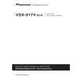
Step 3-5: VIDEO CLK, DATA
IC701 (Pin 48) LLC1
Step 3-3: Reset
CN318 (Pin 2) XVCRST
e A
C
Is there a clock (27 MHz)? Yes IC701 (Pins 2 to 9)
No Check the parts and patterns in the path (IC401). If IC401 is failure, replace IC401.
Is the voltage "H" (5 V)?
No Diagnose between the BOARD TO BOARD Assy and MAIN Assy.
P8 to P15
X'tal
Yes
f
IC401 (Pin 22) Is there the CLK (28.63636MHz) ? Yes
D
XTAL
c
No Check the X401 or IC402. If X401 or IC402 is failure, replace X401 or IC402.
Is there a data?
No Check the parts and patterns in the path. If IC401 is failure, replace IC401.
Yes
Step 3-6: Video Output
IC701 (Pin 35) DACA
Step 3-4: I2C
CN318 (Pin 4) Does a signal output in constant period (0 to 5 V) ? Yes
E
g-1
VCSDA Is there a composite signal? Yes CN316 (Pin 21) No Check the parts and patterns in the path. If IC701 or R731 or R732 or Q731 is failure, replace it. CVBS OUT
A
No Diagnose between the BOARD TO BOARD Assy and MAIN Assy.
a
VCSCL Is there a composite signal? Yes IC701 (Pin 33) DACB No Check the parts and patterns in the path. If Q731 or R733 is failure, replace Q731 or R733. No Diagnose between the BOARD TO BOARD Assy and MAIN Assy.
CN318 (Pin 3)
A
Does a clock output in constant period (0 to 5 V) ? Yes
g-2
Is there a Y signal? Yes No Check the parts and patterns in the path. If IC701 or R741 or R742 or Q741 is failure, replace it.
F
D
112
1 2
VSX-917V-K
3 4
|
|
|
> |
|