|
|
|
Categories
|
|
Information
|
|
Featured Product
|
|
|
 |
|
|
There are currently no product reviews.
 ;
Great Service Manual, Very Complete, as advertised, Perfect, Thanks!
 ;
Good quality service manual.It has helped me to fix my FV1800,particularly for replacing the dial cord.The scheme is on A3 format and very readable.Thank.Olivier.
;
This manual is complete and very readable.It was a great help for my two ICF5800L.The first one had the dial cord broken,and without the service manual it is impossible to replace it.Thank.Olivier.
;
This is a top quality manual. You couldn't get better if you had the original and scanned it yourself. Best price on the net as well. Diagrams are clear and complete, text is sharp and easy to read. Granted you don't get the manual the second you click pay, but the few hours you have to wait for it to be available for download isn't a problem at all. This is a very reliable company.
Very VERY pleased with the product, and will buy others. Thanks!
;
In a word AWESOME.
I never expected the quality and abundant content that I got with this manual. Everything you'd ever want to know from a service perspective is found in this manual, along with... as a bonus, operating instructions on how to use the unit. WOW. Very impressed with the quality of the manual. You won't be disappointed if you're looking for the EVS900 service manual.
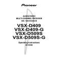
ORDER NO.
RRV2294
AUDIO/VIDEO MULTI-CHANNEL RECEIVER
VSX-D509S
VSX-D509S-G VSX-D409 VSX-D409-G
Type
BXJI HLXJI � �
THIS MANUAL IS APPLICABLE TO THE FOLLOWING MODEL(S) AND TYPE(S).
Model VSX-D509S VSX-D509S-G VSX-D409 VSX-D409-G Power Requirement The voltage can be converted by the following method.
AC240V, �
AC110V/120-127V/220V/240V With the voltage selector AC220-230V
� : Alter the wiring of the Power-supply block at the primary winding of Power-transformer referring to the "Line Voltage Selection" described
in this Manual.
¶ This service manual should be used together with the following manual(s):
Model No.
VSX-709RDS/MYXJIEW VSX-609RDS/MYXJIEW
Order No.
RRV2274
Remarks
CONTENTS
1. CONTRAST OF MISCELLANEOUS PARTS ........ 2 2. SCHEMATIC DIAGRAM ....................................... 7 3. PCB CONNECTION DIAGRAM .......................... 10
4-1, Meguro 1-chome, Meguro-ku, Tokyo 153-8654, Japan PIONEER ELECTRONICS SERVICE, INC. P.O. Box 1760, Long Beach, CA 90801-1760, U.S.A. PIONEER EUROPE NV Haven 1087, Keetberglaan 1, 9120 Melsele, Belgium PIONEER ELECTRONICS ASIACENTRE PTE. LTD. 253 Alexandra Road, #04-01, Singapore 159936
PIONEER CORPORATION
PIONEER CORPORATION 2000
T � ZZK MAY 2000 Printed in Japan
|
|
|
> |
|