|
|
|
Categories
|
|
Information
|
|
Featured Product
|
|
|
 |
|
|
There are currently no product reviews.
 ;
Great and quick support. The maual was exactly what I was looking for and my problem
solved. Many thanks.
;
Very good service Within one day i received a pdf of the users manual and electric circuits so I was able to measure the different voltages in the printed circuit and find out the fault Payment was also reliable and easy.Without the manual i could not have repaired.So thanks to "Search for a manual"
 ;
you are doing great job guys.....my father ask me to find out the schematics of Sony KV25R1D to sort out the problem ..(he was electrical technician, and excperianced with TV and simillar stuff). finally he found the cause and change all necessary parts....now he has got working old dog..and is very happy!!... thank you all.. NB..he also saved the repair cost.
;
Perfect. Received my manual within 24 hours. Clear scan of the manual I needed. No problem.
;
Item as described, very well detailed manual with complete schematics. I've received the download information shortly after payment, very good support.
5
6
7
8
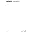
Step 7: 1st DSP f
CN401 (Pin 20) RESET
j
CN401 (Pin 16)
For the following diagnosis, a digital oscilloscope must be used. SPICLK
A
Is the logic of RST_1 "H" ?
No
Check the output from the DIGITAL MOTHER Assy.
w
Yes R139
Is the clock signal output while the voltage at SPIDS_1 is "L"?
No
Check the output from the DIGITAL MOTHER Assy.
y
Yes R144
Is the logic of RST_1 "H" ? Yes
No
Check the resistors and patterns in the path.
Is the clock signal output while the voltage at SPIDS_1 is "L"?
No
Check the resistors and patterns in the path.
B
Is the logic of RST_1 maintained at "H"? (Does it fall to become "L" periodically?)
k
No It is likely a boot error. (It is very difficult to diagnose which peripheral part of the DSP is in failure.)
Yes CN401 (Pin 19) MOSI
g
Yes R134 REQ_1
Is the clock signal output while the voltage at SPIDS_1 is "L"?
No
Check the output from the DIGITAL MOTHER Assy.
C
z
Does the logic become "H" for a moment when the input stream is changed? No The 1st DSP is in failure. Replace it.
Yes R146
g
Yes CN401 (Pin 21)
Is the clock signal output while the voltage at SPIDS_1 is "L"?
No
Check the resistors and patterns in the path.
AA
Does the logic become "H" for a moment when the input stream is changed? No Check the resistors and patterns in the path.
Yes R142 MISO
h
Yes CN401 (Pin 17) SPIDS_1
Is the clock signal output while the voltage at SPIDS_1 is "L"?
D
No The 1st DSP is in failure. Replace it.
i
Does the logic become "L" for a moment when the input stream is changed? No Check the output from the DIGITAL MOTHER Assy.
Yes CN401 (Pin 18)
x
Yes R137
Is the clock signal output while the voltage at SPIDS_1 is "L"? Yes
No
Check the resistors and patterns in the path.
E
Does the logic become "L" for a moment when the input stream is changed? Yes
No
Check the resistors and patterns in the path.
It is very difficult to diagnose which part is in failure.
F
VSX-LX70
5 6 7 8
35
|
|
|
> |
|