|
|
|
Categories
|
|
Information
|
|
Featured Product
|
|
|
 |
|
|
There are currently no product reviews.
 ;
I am very happy regarding the online purchase of this manual from Owner-Manuals.com as with this I could set right my Denon CD player and Amplifier.
I once again sincerely thank them for the prompt service which was rendered to me.
N. Shanker
;
More than pleased with my prurchase, very good product for the price.
;
Manual-link came 30 minutes after having paid for an extremely rare (40 years old) item (sony icr-120) and helped me to get the radio rework again. So really good help for me, fast and reliable delivery and -taken that into consideration- a very reasonable price for that service. So thanks again! Mike, Germany
 ;
Some of the pictures in this manual are a bit irritating. I had to dissassemble the unit and some of the screws have different threads, which is not mentioned in this manual. Also some of the drawings of the boards look different than the actual boards.
After all, the manual was very useful. I was able to recalibrate the capstan drive and it is working fine again.
;
This manual is very good. 303 pages scanned in a very high resolution. My camera has bad, leaking capacitors which all of the V5000 models are suffering from these days.
There is a huge part list with all capacitors, transistors etc. in this manual which helped me a lot. Otherwise I would not have been able to buy replacement parts.
The dissassembly guide is very enormous and detailed. Unlike on the Panasonic MS1 manual I downloaded here it actually looks like the real parts look. And the screws are labeled correctly, so you shouldn't have any left after the repair. ;)
15 July 1994
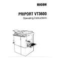
SCANNER SECTION
[C] [B]
[C] [B] [E]
[D] 3. Put the positioning pins in the front and rear holes [B] of the first scanner. Make sure that the positioning pin can be set in the holes smoothly. 4. If the pins did not fit smoothly, adjust the position of the first scanner with the screws [C]. 5. Check and adjust the position of the second scanner using the same procedure as in steps 3 and 4. 6. Slide the scanner unit and remove the sensor cover [D] (2 screws). 7. Connect the probes of the multimeter to the sensor�s connector. CN1: +5V CN2: GND CN3: Scanner H.P (Signal) 8. Slide the sensor bracket [E] and tighten the bracket when the sensor output goes to low (5 V to 0 V). 9. Check the optics adjustments and adjust them if necessary (see section 3).
5-3
 $4.99 VT3600 RICOH
Owner's Manual Complete owner's manual in digital format. The manual will be available for download as PDF file aft…
|
|
|
> |
|