|
|
|
Categories
|
|
Information
|
|
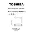
Featured Product
|
|
|
 |
|
|
There are currently no product reviews.
 ;
Caracteristiques,circuit adjusment,notes on schematis diagram,it's a good service manual,to live well,thanks.
;
Service Manual in good quality, with all of the pages.
;
Very usrfull for repaur, great quality copy. includes complete parts list and schematics
;
Good quality Service Manual, availability of components includes disassembly, electronic adjustments. Includes a full list of details and diagrams. Contains 58 pages.
 ;
y'm hapy for this shoping . Estoy feliz por esta compra , ahora puedo reparar mi equipo de audio que AMO . And very good price for this manual . Thank yuo .
DISASSEMBLY INSTRUCTIONS
3. REMOVAL OF ANODE CAP
Read the following NOTED items before starting work. * After turning the power off there might still be a potential voltage that is very dangerous. When removing the Anode Cap, make sure to discharge the Anode Cap's potential voltage. * Do not use pliers to loosen or tighten the Anode Cap terminal, this may cause the spring to be damaged. REMOVAL 1. Follow the steps as follows to discharge the Anode Cap. (Refer to Fig. 3-1.) Connect one end of an Alligator Clip to the metal part of a flat-blade screwdriver and the other end to ground. While holding the plastic part of the insulated Screwdriver, touch the support of the Anode with the tip of the Screwdriver. A cracking noise will be heard as the voltage is discharged. 3. After one side is removed, pull in the opposite direction to remove the other. NOTE Take care not to damage the Rubber Cap. INSTALLATION 1. Clean the spot where the cap was located with a small amount of alcohol. (Refer to Fig. 3-3.) NOTE Confirm that there is no dirt, dust, etc. at the spot where the cap was located.
Location of Anode Cap
GND on the CRT
Fig. 3-3 2. Arrange the wire of the Anode Cap and make sure the wire is not twisted. 3. Turn over the Rubber Cap. (Refer to Fig. 3-4.)
Screwdriver Support Alligator Clip GND on the CRT
CRT
Fig. 3-1
Fig. 3-4 4. Insert one end of the Anode Support into the anode button, then the other as shown in Fig. 3-5.
2. Flip up the sides of the Rubber Cap in the direction of the arrow and remove one side of the support. (Refer to Fig. 3-2.) Rubber Cap
CRT Support Fig. 3-2
CRT
Support Fig. 3-5
5. Confirm that the Support is securely connected. 6. Put on the Rubber Cap without moving any parts.
B3-1
|
|
|
> |
|