|
|
|
Categories
|
|
Information
|
|
Featured Product
|
|
|
 |
|
|
There are currently no product reviews.
 ;
The content of the manual was not found on the Internet and was a hard find. I check the net for 5 hours until I came across this web-site. When I did find the book it Auto loaded into my IPAD PDF shelf for books for review at anytime. Overall I am satisfied with the book and it answered all my questions. This repair book is obsolete because the product I bout it for is pretty old. Thanks for the help with the download and even having the manual. Thanks 73's K5HRD
;
Excellent manual including schematics. The service was great and the manual helped complete the job.
;
It was magic after so many years to still be able to source this info. It was equally amazing to return my Pioneer receiver to it near new sound quality AFTER NEARLY 30 YEARS! Thank you for this ability!
;
Very quick and easy website to use and fast download of manual, quality of manual is excellent and will be pleased to use this service again in the future, thanks so much!
 ;
Easy and secure way to get a complete service manual of a vintage hifi component. Only some parts of the print copy are dificult to read. Nice price!
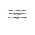
3. DISASSEMBLY AND REPLACEMENT
3-1. Removal of the FRONT LOADING Ass�y (Fig. 3.1)
NOTE: Remove the FRONT LOADING Ass�y in eject mode. a. Unscrew the 2 screw holding the F/L ass�y. b. Separate the F/L Ass�y from the MAINBASE ass�y by lifting the rear part of F/L (Screw Hole).
3-2. Disassembly of FRONT LOADING Ass�y (FIg. 3.2~3.5)
a. Remove the washer holding the door opener and separate F/L Assembly by moving the DOOR OPENER in the direction of arrow. b. Remove the 2 screw holding the TOP PLATE and separate the CASSETTE HOLDER Ass�y by moving the FL BRKT L and FL BRKT R in the direction of arrow. (Fig. 3.2)
Fig. 3.1 Removal of the FRONT LOADING Ass�y
FIg. 3.2 Disassembly of the FRONT LOADING Ass�y
11
|
|
|
> |
|