|
|
|
Categories
|
|
Information
|
|
Featured Product
|
|
|
 |
|
|
There are currently no product reviews.
 ;
Superb rendition. Drawings (schematics) complete and unabridged. I do a great deal of vintage audio restoration. Documentation is essential for successful repairs. I have found sources over the years that offer good documentation, but rarely all that is necessary. Owner's Manuals has filled that void with complete and legible documentation. They have narrowed my "favorites" to a more manageable collection. This Denon manual in particular contained the latest revisions level, and offered alterations favorable to updating the item. The Illustrated Parts Breakdown (IPB) was well enough detailed to simplify part symbols and physical locations. You will not be disappointed!
;
Clear and concise. Saved me a lot of time and money.
;
Superb manual. Exactly what I ordered and made available in a very timely manner.
 ;
very fast detailed and accurate hope to do business again
;
This was precisely what I was looking for. Complete and good quality!
2-3
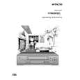
2. Einbau von FLATPACK - Bauteile a. Verwenden Sie eine Ablötlitze, um Lötrückstände an den Lötaugen des Prints zu entfernen. Damit wird die Montage der neuen FLATPACK-Schaltung erleichtert. b. Die Markierung ��� auf der Flatpack-Schaltung kennzeichnet Pin1. Diese Markierung mu� mit dem Kontakt 1 auf dem Print übereinstimmen. Löten Sie die vier Ecken der Schaltung an (siehe Abb. 2-9).
Spannungsmessungen
Farbtestbalken bei AUFNAHME und WIEDERGABE bei Normalgeschwindigkeit. Anmerkung: Die Spannungen bei AUFNAHME und WIEDERGABE sind in den Diagrammen gemä� nachstehender Abbildung angegeben.
BEISPIEL
AUFNAHME u. WIEDERGABE (gleiche Spannung für beide Modi) WIEDERGABE-Mode Pin 1 der FLATPACK-Schaltung ist mit der Markierung ��� gekennzeichnet. Abb. 2-9 AUFNAHMEMode Abb. 2-11
Vorlöten Lötkolben
Oszillogramme
1
Me�punkt Amplitude Zeitbasis Betriebsmode
2 3 Print FLATPACKSchaltung Abb. 2-10 c. Löten Sie alle Pins der Flatpack-Schaltung an, wobei darauf zu achten ist, da� kein Kurzschlu� zwischen den Pins entsteht. 4
4
Anmerkung
Alle integrierten Schaltungen sowie zahlreiche andere Halbleiter sind empfindlich gegen elektrostatische Entladungen und sind daher gemä� den Vorschriften im Kapitel �Sicherheitshinweise� zu behandeln.
2
1
Abb. 2-12
3
Spannung der Z-Dioden
Die Z-Spannung der Z-Dioden wird als solche in den Schaltungen ausgewiesen: Beispiel: BZX79C20............Z-Spannung: 20 Volt
D
|
|
|
> |
|