|
|
|
Categories
|
|
Information
|
|
Featured Product
|
|
|
 |
|
|
There are currently no product reviews.
 ;
An excellent document to assist in the repair of my old personal tape player. It includes full circuit diagrams and physical layout drawings and full instructions on disassembly and fault finding.
Well worth the meagre price.
;
Very good conversation, Pretty fast Service, wood do it again,
Have paid by Paypal, so i got the Service Manual online after 15 Min.
Very helpfully.
Greeting from Germany,
Hans
;
Good-quality scans. Detailed description. I hope I can repair the machine.
;
High-quality scanning. Detailed description. Recommend for all technician. A+++
;
This is a good quality scan of the original Service Manual from Nordmende, Germany. Contains the circuit diagram, PCB layout, adjust/tune instructions as well. It is NOT in English but in GERMAN language! That was quite right for my german friend from the lower east side in Berlin.
ELECTRICAL ADJUSTMENTS
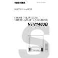
2-3: RF AGC 1. Place the set with Aging Test for more than 15 minutes. 2. Receive the UHF (63dB). 3. Connect the digital voltmeter between the pin 5 of CP603 and the pin 1 (GND) of CP603. 4. Activate the adjustment mode display of Fig. 1-1 and press the channel button (01) on the remote control to select "RF AGC". 5. Press the VOL. UP/DOWN button on the remote control until the digital voltmeter is 2.3 ± 0.1V. 2-8: VERTICAL SIZE NOTE: Adjust after performing adjustments in section 2-7. 1. Receive the monoscope pattern from the Pattern Generator. 2. Using the remote control, set the brightness and contrast to normal position. 3. Activate the adjustment mode display of Fig. 1-1 and press the channel button (11) on the remote control to select "V SIZE (50)". 4. Adjust by using the VOL. UP/DOWN button on the remote control so that the Up/Down OVER SCAN Quantity becomes equal to the Right/Left OVER SCAN Quantity. 5. Receive a broadcast and check if the picture is normal. 6. Receive the monoscope pattern of NTSC. (Audio Video Input) 7. Press the AV button on the remote control to set to the AV mode. Then perform the above adjustments 2~4. 2-9: VERTICAL LINEARITY NOTE: Adjust after performing adjustments in section 2-8. After the adjustment of Vertical Linearity, reconfirm the Vertical Position and Vertical Size adjustments. 1. Receive the monoscope pattern from the Pattern Generator. 2. Using the remote control, set the brightness and contrast to normal position. 3. Adjust the VR401 until the SHIFT quantity of the OVER SCAN on upside and downside becomes minimum. 2-10: OSD HORIZONTAL 1. Using the remote control, set the brightness and contrast to normal position. 2. Activate the adjustment mode display of Fig. 1-1 and press the channel button (31) on the remote control to select "H POS OSD". 3. Press the VOL. UP/DOWN button on the remote control until the difference of A and B becomes minimum. (Refer to Fig. 2-2)
(TV SECTION)
2-4: CONSTANT VOLTAGE 1. Connect the digital voltmeter to TP501. 2. Set condition is AV MODE without signal. 3. Using the remote control, set the brightness and contrast to normal position. 4. Adjust the VR502 until the digital voltmeter is 134 ± 1V. 2-5: FOCUS 1. Receive a broadcast. 2. Turn the Focus Volume fully counterclockwise once. 3. Adjust the Focus Volume until picture is distinct. 2-6: HORIZONTAL POSITION 1. Receive the monoscope pattern from the Pattern Generator. 2. Using the remote control, set the brightness and contrast to normal position. 3. Activate the adjustment mode display of Fig. 1-1 and press the channel button (08) on the remote control to select "H POSI (50)". 4. Press the VOL. UP/DOWN button on the remote control until the SHIFT quantity of the OVER SCAN on right and left becomes minimum. 5. Receive the monoscope pattern of NTSC. (Audio Video Input) 6. Press the AV button on the remote control to set to the AV mode. Then perform the above adjustments 2~4. 2-7: VERTICAL POSITION NOTE: Adjust after performing adjustments in section 2-6. 1. Receive the monoscope pattern from the Pattern Generator. 2. Using the remote control, set the brightness and contrast to normal position. 3. Activate the adjustment mode display of Fig. 1-1 and press the channel button (09) on the remote control to select "V POSI (50)". 4. Check if the step No. V. POSI (50) is "05". 5. Adjust the VR402 until the horizontal line becomes fit to the notch of the shadow mask. 6. Receive the monoscope pattern of NTSC. (Audio Video Input) 7. Activate the adjustment mode display of Fig. 1-1 and press the channel button (09) on the remote control to select "V POSI (60)". 8. Check if the step No. V. POSI (60) is "15".
( PAL) TV
31 H POS OSD 35
A 2-11: CUT OFF
B
Fig. 2-2
1. Set condition is AV MODE without signal. 2. Using the remote control, set the brightness and contrast to normal position. 3. Place the set with Aging Test for more than 15 minutes. 4. Activate the adjustment mode display of Fig. 1-1 and press the channel button (00) on the remote control to select "CUT OFF". 5. Adjust the Screen Volume until a dim raster is obtained.
D3-2
|
|
|
> |
|