|
There are currently no product reviews.
 ;
I am satisfied with the service. And if need another manual, i will definitely buy from this site. Keep up the good work.
;
have download a number of manuals todate , most are excellant, one or two sometimes a little difficult to read but a least avaialable, great site .
Brad.
;
Excellent had everything I wanted, very happy with purchase
 ;
This service is relatively cheap, document is fast available, schematic is readable.
Thanks.
;
So far I´m a satisfied customer. I have only downloaded "TECHNICS SX-KN470 Service Manual" maybe I will use it later.
Best regards
Peter
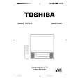
DISASSEMBLY INSTRUCTIONS
1-5: DECK SHIELD PLATE (Refer to Fig. 1-5) 1. Remove the 2 screws 1. 2. Remove the Deck Shield Plate in the direction of arrow (A). 3. Remove the screw 2. 4. Remove the Bottom Shield Plate in the direction of arrow (B).
1
Deck Shield Plate
1-7: JACK PLATE AND SYSCON PCB (Refer to Fig. 1-7) 1. Remove the screw 1. 2. Remove the 2 screws 2. 3. Remove the Syscon PCB in the direction of arrow.
Syscon PCB
1 1
(A)
2 2
TV/VCR Block
(B)
Deck Holder
Fig. 1-7
Bottom Shield Plate
2
Fig. 1-5
1-6: DECK CHASSIS (Refer to Fig. 1-6) NOTE Do not remove the cable at the FE Head section. The FE Head may be damaged if you remove the cable by force. 1. Remove the screw 1. 2. Remove the FE Head. 3. Remove the 3 screws 2. 4. Disconnect the following connectors: (CP1001, CP4001, CP4004 and CP4005). 5. Remove the Deck Chassis in the direction of arrow.
2 2
1
FE Head
2
Deck Chassis
Syscon PCB
Fig. 1-6 B1-2
|