|
|
|
Categories
|
|
Information
|
|
Featured Product
|
|
|
 |
|
|
There are currently no product reviews.
 ;
Great quality manual, fast service, excellent seller... Thanks !!!
;
Great manual and fast service. Download was possible after a few hours.
;
thanks a lot.
without the service manual my handycam was going to the trash.
good job, go on.
bye
 ;
This service manual is a good copy of the original, complete and fully readable. It is really useful to repair my Tv set following its clear instructions.
;
Excellent quality. Easy process to download. No issues or problems at all - was exactly what I was looking for and needed. Great service.
ELECTRICAL ADJUSTMENTS
(REC TUNER) 1. Place the set with Aging Test for more than 10 minutes. 2. Connect the oscillator (39.5MHz) to TP6001. 3. Connect the digital voltmeter between the pin 7 of CP603 and the pin 1 (GND) of CP603. 4. Adjust the L6006 until the digital voltmeter is 2.4 ± 0.1V. 2-3: RF AGC (MONITOR TUNER) 1. Place the set with Aging Test for more than 15 minutes. 2. Receive the UHF (63 ± 1dB). 3. Connect the digital voltmeter between the pin 5 of CP603 and the pin 1 (GND) of CP603. 4. Activate the adjustment mode display of Fig. 1-1 and press the channel button (01) on the remote control to select "RF AGC". 5. Press the LEFT/RIGHT button on the remote control until the digital voltmeter is 2.5 ± 0.1V. (REC TUNER) 1. Place the set with Aging Test for more than 15 minutes. 2. Receive the UHF (63 ± 1dB). 3. Connect the digital voltmeter between the pin 6 of CP603 and the pin 1 (GND) of CP603. 4. Activate the adjustment mode display of Fig. 1-1 and press the channel button (39) on the remote control to select "REC AGC". 5. Press the LEFT/RIGHT button on the remote control until the digital voltmeter is 3.3 ± 0.1V. 2-7: VERTICAL POSITION NOTE: Adjust after performing adjustments in section 2-6. 1. Receive the monoscope pattern from the Pattern Generator. 2. Using the remote control, set the brightness and contrast to normal position. 3. Activate the adjustment mode display of Fig. 1-1 and press the channel button (09) on the remote control to select "V POSI (50)". 4. Check if the step No. V. POSI (50) is "05". 5. Adjust the VR402 until the horizontal line becomes fit to the notch of the shadow mask. 6. Receive the cross hatch signal of NTSC. (Audio Video Input) 7. Press the AV button on the remote control to set to the AV mode. 8. Using the remote control, set the brightness and contrast to normal position. 9. Activate the adjustment mode display of Fig. 1-1 and press the channel button (09) on the remote control to select "V POSI (60)". 10. Check if the step No. V. POSI (60) is "15". 2-8: VERTICAL SIZE NOTE: Adjust after performing adjustments in section 2-7. 1. Receive the monoscope pattern from the Pattern Generator. 2. Using the remote control, set the brightness and contrast to normal position. 3. Activate the adjustment mode display of Fig. 1-1 and press the channel button (11) on the remote control to select "V SIZE (50)". 4. Adjust by using the LEFT/RIGHT button on the remote control so that the Up/Down OVER SCAN Quantity becomes equal to the Right/Left OVER SCAN Quantity. 5. Receive a broadcast and check if the picture is normal. 6. Receive the cross hatch signal of NTSC. (Audio Video Input) 7. Press the AV button on the remote control to set to the AV mode. Then perform the above adjustments 2~4. 2-9: VERTICAL LINEARITY NOTE: Adjust after performing adjustments in section 2-8. After the adjustment of Vertical Linearity, reconfirm the Vertical Position and Vertical Size adjustments. 1. Receive the monoscope pattern from the Pattern Generator. 2. Using the remote control, set the brightness and contrast to normal position. 3. Adjust the VR401 until the SHIFT quantity of the OVER SCAN on upside and downside becomes minimum.
(TV SECTION)
2-4: CONSTANT VOLTAGE 1. Connect the digital voltmeter to TP401. 2. Set condition is AV MODE without signal. 3. Using the remote control, set the brightness and contrast to normal position. 4. Adjust the VR1701 until the digital voltmeter is 115 ± 1V. 2-5: FOCUS 1. Receive a broadcast. 2. Turn the Focus Volume fully counterclockwise once. 3. Adjust the Focus Volume until picture is distinct. 2-6: HORIZONTAL POSITION 1. Receive the monoscope pattern from the Pattern Generator. 2. Using the remote control, set the brightness and contrast to normal position. 3. Activate the adjustment mode display of Fig. 1-1 and press the channel button (08) on the remote control to select "H POSI (50)". 4. Press the LEFT/RIGHT button on the remote control until the SHIFT quantity of the OVER SCAN on right and left becomes minimum. 5. Receive the cross hatch signal of NTSC. (Audio Video Input) 6. Press the AV button on the remote control to set to the AV mode. Then perform the above adjustments 2~4.
D3-2
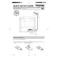 $4.99 VTW2186 TOSHIBA
Quick Start Quick start guide ( sometimes called quick guide ) contains most important information on how to use…
|
|
|
> |
|