|
|
|
Categories
|
|
Information
|
|
Featured Product
|
|
|
 |
|
|
There are currently no product reviews.
 ;
very good manual with clear electrical schemes. Very helpful to find wat was wrong inside my microwave.
 ;
Hi, thankyou for providing the Nordmende Globetrotter original manufacturer's repair manual. Quality is very good and sharp - the PDF file was comfortably small to download. The only question is: why did it take so long to become ready for download?? Many thanks anyway, I fixed the fault in the radio thanks to the circuit.
regards: Nick
;
This was super service.Ordered this manual and was reading the download an hour later
;
as always, rapid and efficient, very good and clear prints
details clearly visible keep going this way!!!!!!
;
I expect a wonderful result as alaways!!!!!!
Usually is much faster....
ELECTRICAL ADJUSTMENTS
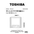
(REC TUNER) 1. Place the set in Aging Test for more than 10 minutes. 2. Connect the oscillator (39.5MHz) to TP6001. 3. Connect the digital voltmeter between the pin 7 of CP603 and the pin 1 (GND) of CP603. 4. Adjust the L6006 until the digital voltmeter is 2.4 ± 0.1V. 2-3: RF AGC (MONITOR TUNER) 1. Place the set in Aging Test for more than 15 minutes. 2. Receive the UHF (63 ± 1dB). 3. Connect the digital voltmeter between the pin 5 of CP603 and the pin 1 (GND) of CP603. 4. Activate the adjustment mode display of Fig. 1-1 and press the channel button (01) on the remote control to select "RF AGC". 5. Press the LEFT/RIGHT button on the remote control until the digital voltmeter is 2.5 ± 0.1V. (REC TUNER) 1. Place the set in Aging Test for more than 15 minutes. 2. Receive the UHF (63 ± 1dB). 3. Connect the digital voltmeter between the pin 6 of CP603 and the pin 1 (GND) of CP603. 4. Activate the adjustment mode display of Fig. 1-1 and press the channel button (39) on the remote control to select "REC AGC". 5. Press the LEFT/RIGHT button on the remote control until the digital voltmeter is 3.3 ± 0.1V. 2-7: VERTICAL POSITION NOTE: Adjust after performing adjustments in section 2-6. 1. Receive the monoscope pattern from the Pattern Generator. 2. Using the remote control, set the brightness and contrast to normal position. 3. Activate the adjustment mode display of Fig. 1-1 and press the channel button (09) on the remote control to select "V POSI (50)". 4. Check if the step No. V. POSI (50) is "05". 5. Adjust the VR402 until the horizontal line becomes fit to the notch of the shadow mask. 6. Receive the cross hatch signal of NTSC. (Audio Video Input) 7. Press the AV button on the remote control to set to the AV mode. 8. Using the remote control, set the brightness and contrast to normal position. 9. Activate the adjustment mode display of Fig. 1-1 and press the channel button (09) on the remote control to select "V POSI (60)". 10. Check if the step No. V. POSI (60) is "15".
horizontal line
;; ;; ;; ; ;; ;; ;; ;;
Notch
(TV SECTION)
2-4: CONSTANT VOLTAGE 1. Connect the digital voltmeter to TP401. 2. Place the set in AV MODE without signal. 3. Using the remote control, set the brightness and contrast to normal position. 4. Adjust the VR1701 until the digital voltmeter is 115 ± 1V. 2-5: FOCUS 1. Receive a broadcast. 2. Turn the Focus Volume fully counterclockwise once. 3. Adjust the Focus Volume until picture is distinct. 2-6: HORIZONTAL POSITION 1. Receive the monoscope pattern from the Pattern Generator. 2. Using the remote control, set the brightness and contrast to normal position. 3. Activate the adjustment mode display of Fig. 1-1 and press the channel button (08) on the remote control to select "H POSI (50)". 4. Press the LEFT/RIGHT button on the remote control until the SHIFT quantity of the OVER SCAN on right and left becomes minimum. 5. Receive the cross hatch signal of NTSC. (Audio Video Input) 6. Press the AV button on the remote control to set to the AV mode. Then perform the above adjustments 2~4. 2-8: VERTICAL SIZE
Shadow mask Fig. 2-2
NOTE: Adjust after performing adjustments in section 2-7. 1. Receive the monoscope pattern from the Pattern Generator. 2. Using the remote control, set the brightness and contrast to normal position. 3. Activate the adjustment mode display of Fig. 1-1 and press the channel button (11) on the remote control to select "V SIZE (50)". 4. Adjust by using the LEFT/RIGHT button on the remote control so that the Up/Down OVER SCAN Quantity becomes equal to the Right/Left OVER SCAN Quantity. 5. Receive a broadcast and check if the picture is normal. 6. Receive the cross hatch signal of NTSC. (Audio Video Input) 7. Press the AV button on the remote control to set to the AV mode. Then perform the above adjustments 2~4. 2-9: VERTICAL LINEARITY NOTE: Adjust after performing adjustments in section 2-8. After the adjustment of Vertical Linearity, reconfirm the Vertical Position and Vertical Size adjustments. 1. Receive the monoscope pattern from the Pattern Generator. 2. Using the remote control, set the brightness and contrast to normal position. 3. Adjust the VR401 until the SHIFT quantity of the OVER SCAN on upside and downside becomes minimum. D3-2
|
|
|
> |
|