|
|
|
Categories
|
|
Information
|
|
Featured Product
|
|
|
 |
|
|
There are currently no product reviews.
 ;
My first manual from Owner-Manuals.com but not the last! I am very satisfied with the easy ordering and promt delivery of a manual I did not find anywhere else.
 ;
This manual is very helpfull to use the Power Supply. All technical information has been available.
For service use the circuit diagrams are very good.
Thanks .
;
Very comprehensive document which is a must-have for any Satellit 2100 owner whose set up is somewhat intricate. Due to the bad quality of the pictures that are rather dark and a bit blurred I gave 4-star feedback.
;
The manual was missing 2 pages but when I presented the problem to the company they made every attempt to get the 2 pages to me, when they couldn't they refunded my money. A very pleasing and easy transaction. The manual they provided was the original, it was concise and to the point. I plan to do business with this company again when should the need arise.
;
The owners manual is very good. all my how to questions were answered in detail.
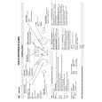
Installation and Connection (WB-1550)
Disassembling the Housing
1.
Main Housing Unit Screw A (M4 x 6) x 3
Dismantle the gasket and gasket gland
Loosen the 8 Screws B (M4) using a driver, followed by dismantling the gasket and gasket gland from the lower housing. T The 8 Screws B (M4) cannot be totally removed from the gasket to prevent it from falling off.
2.
Dismantle the lower housing
Loosen the 3 Screws A (M4 x 6) using a driver, followed by dismantling the lower housing from the main housing unit. T The lower housing is connected to the main housing unit using a safety wire.
2.
Lower Housing Safety Wire Gasket
1.
Gasket Gland
Screw B (M4) x 8
Procedures Before Mounting the Camera
1.
Rubber Gasket (White)
1.
Dismantle the rubber gasket of the camera�s ceiling mount
Dismantle the rubber gasket (white) on the same side as the ceiling mount of the combination camera to be installed.
2.
Ceiling Mount
Dismantle the rubber gasket in the interior of the camera
2.
A B
Camera Body Cover Main Unit Camera Body Cover
Follow the procedures below to remove the rubber gasket from the interior of the combination camera. A Turn the camera body cover in the direction as indicated in the left diagram. (When the camera body cover is tight and cannot be turned, do so upon fastening the main unit.) B Dismantle the camera body cover. C Dismantle the dome cover. D Remove the rubber gasket and restore the dome cover and camera body cover to their original positions. CAUTION: � The combination camera is an enclosed unit. In order to prevent fogging in the interior of the dome cover, ensure to remove the rubber gasket (2 types) before use. � Do not remove the combination camera from the housing and use it singly after removing the rubber gasket and installing to the housing. Doing so may cause the camera to malfunction.
C
Dome Cover
D
Dome Cover
Rubber Gasket
Rubber Gasket
10
|
|
|
> |
|