|
|
|
Categories
|
|
Information
|
|
Featured Product
|
|
|
 |
|
|
There are currently no product reviews.
 ;
Good scan, very handy and it also includes the user manual. 122 pages in total.
;
This manual was exactly what I needed. Detailed, useful and delivered as promised.
 ;
Great manual good quality really helped in the repair of my Toshiba, thanks
;
Print was clear and easy to read. Thank you Joe joeoldaudio
;
Very great deal. In a few minutes a have the manual, that I needed. Thanl you very much
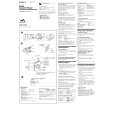
WM-FX495 SECTION 1 SERVICING NOTES
This set detects the rotation of the idler gear (A) (side S) using the photo reflector (PH751). The PH751 is mounted on the MAIN board, therefore the idler gear (A) (side S) cannot be detected with the MAIN board removed. As a result, the motor (M601) cannot be controlled, causing malfunction. Further, the MD CONT switch (S601) is also mounted on the MAIN board, and with the board removed, the mechanism position cannot be detected and the operation is not changed over. Therefore, when the voltage check is executed with the MAIN board removed, follow the procedure provided below. 1. Setting 1) Refer to �3. DISASSEMBLY�, and remove the MAIN board. 2) Connect the MAIN board to the motor (M601) using jumper wires. These can be connected easily with the use of the extension tool (Part No. 1-769-143-11) (ten in one set). 3) Connect the AF oscillator to the TP752 and the BT401 (BATT� ). 4) Supply 1.5 V to the battery terminals using the regulated power supply. 2. Preset state To set the PLAY, FF, REW modes, the preset state must be set. 1) Check that the slider (NRA) and the MD CONT switch (S601) are set to the center position. If not, set the preset state as follow. 2) Move the MD CONT switch (S601) to the side, which the slider (NRA) is facing. 3) The slider (NRA) will move when the regulated power supply switch is set to OFF once and then set to ON. Move the MD CONT switch (S601) according to this timing and set to the center position.
� MAIN Board (Component Side) � � MAIN Board (Conductor Side) �
3. FF, REW modes 1) Check that the preset state is set. 2) Input the square wave or sine wave to the TP752 and the BT401 (BATT�). 3) Press the [FF] button or [REW] button . 4. 1) 2) 3) PLAY mode Check that the preset state is set. Input the square wave to the TP752 and the BT401 (BATT�). Press the Y button will move the slider (NRA) once towards the side REV and then to the side FWD. Move the MD CONT switch (S601) according to this timing will set the PLAY mode (side FWD). Press the Y button another time for a second and move the MD CONT switch (S601) according to the movement of the slider (NRA) will set the PLAY mode (side REV).
Note 1: If the above fails, perform from preset again. Note 2: When using headphones, the timing for move the MD CONT switch (S601) can be determined from the beep
sound.
BT401
battery terminal #
PH751
AF oscillator 1k�
TP752 (PHOTO)
RVS REW FF
t
+ �
square wave 2 Hz, 2 VdB 2Vp-p
FWD
S601 (MD CONT)
battery terminal 3 connect to themotor (M601)
3
|
|
|
> |
|