|
|
|
Categories
|
|
Information
|
|
Featured Product
|
|
|
 |
|
 ;
Excellent printing quality.
A complete and very usefull service manual with all details.
GREAT SERVICE AT VERY LOW PRICE!
A+++++++++++++++++++++++++
;
Good,readable manual. I found other manuals that were not readable when it came to part ID, but the one downloaded from owner-manual.com was better than expected. I will do buisness with owner-manual.com again.
;
Service Manual that I received was very helpful to me. Thank you.
;
The manual is well organized and is easy to read. The chapters are following normal way to proceed.
;
This scanned manual is well done in that most all the pages except for one is straight and clear- the way I would do them. One page was upside down but that happens. For the money that is charged on this site you get a pretty good deal. Now with complex repairs, I still prefer to us paper manuals which I have to buy at stereomanuals but the one I got here was much less than the $45 he was charging but this is a larger than normal manual for three different units. I am a picky manual user because I have used original manuals from Sony and Teac.
;
Very useful service manual, was exactly what i needed.Good quality,reasonable price.Thank you.
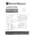
Procedure n Perform the checking with the MIC input connector shortcircuited. (1) Set the spectrum analyzer as follow: CENTER FREQUENCY (fc): CE21 model; 470.125 MHz CE33 model; 566.125 MHz CE62 model; 798.125 MHz CE67 model; 838.125 MHz U14 model; 470.125 MHz U30 model; 566.125 MHz U62 model; 758.125 MHz U66 model; 782.125 MHz REFERENCE LEVEL: 20 dBm FREQUENCY SPAN: 200 kHz (20 kHz/DIV) RBW (resolution band width): 3 kHz VBW (video band width): 1 kHz ATT: 30 dB (2) Decrease gradually the DC output voltage of the DC regulated power supply and confirm that the battery alarm signal turns on at 2 ± 0.2 V. (3) Check that level difference between carrier frequency (center frequency level) on spectrum analyzer and tone signal is with in 29 ±2 dB.
20 dBm
2. Frequency check
Connections (For connecting the DC power supply, refer to the �Preparations� on page 3-2.)
MM-SMA (J)connector with SMA-BNC (J) connector Spectrum analyzer
CN301
Jumper wire TP200
MB-940 Board (A side)
TP501 (GND)
Connect a jumper wire between TP200 and TP501 (GND) by soldering. (TONE signal : OFF).
Procedure n Perform the checking with the Mic input connector (SMC94P) short-circuited. (1) Set the modulation analyzer as follows: MEASUREMENT: FM MEASUREMENT RANGE: ± 40 kHz HPF: 4 kHz LPF: >20 kHz DE EMPHASIS: OFF (2) Set the DC output voltage of DC power supply to 1 ± 0.1 V so that battery alarm signal goes on. (3) Check that frequency counter (resolution:0.1 Hz) reading is 32.782 kHz ±1 Hz. (4) After the checking, remove (unsolder) the jumper wire between TP200 and TP501 (GND) on the MB-940 board (A-side).
29 ±2 dB
V : 10 dB/div H : 20kHz/div fc 32.782 kHz
3-12
WRT-822B
|
|
|
> |
|