|
|
|
Categories
|
|
Information
|
|
Featured Product
|
|
|
 |
|
|
There are currently no product reviews.
 ;
Excellent printing quality.
A complete and very usefull service manual with all details.
GREAT SERVICE AT VERY LOW PRICE!
A+++++++++++++++++++++++++
;
Excellent printing quality.
A complete and very usefull service manual with all details.
GREAT SERVICE AT VERY LOW PRICE!
A+++++++++++++++++++++++++
;
Thank you for providing quickly a manual so old! very good job clear and understandable!
;
Excellent printing quality.
A complete and very usefull service manual with all details.
GREAT SERVICE AT VERY LOW PRICE!
A+++++++++++++++++++++++++
;
Excellent printing quality.
A complete and very usefull service manual with all details.
GREAT SERVICE AT VERY LOW PRICE!
A+++++++++++++++++++++++++
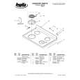
MODELS: WS-48513 / WS-48613 / WS-55513 / WS-55613 / WS-55813 / WS-65513 / WS-65613 / WS-65713 / WS-65813 / WS-73513 / WS-73713
CRT REPLACEMENT
1. Removal of the CRT
Caution! High voltage should be completely discharged prior to CRT removal. Since The CRTs receive high voltage from the HV Block, discharge by shorting the open end of the respective high voltage cable to chassis ground.
Note: Refer to the Cabinet Disassembly Procedures when performing steps 1 through 4. 1. 2. 3. 4. 5. 6. Remove Remove Remove Remove Remove Remove the Speaker Grille, Front Board, and Screen Assy. the Back Board. the Anode Lead Wire from the CR Block. the PCB-CRT. 4 hex-screws "a" retaining the Optical Unit. [Figure 5-1] 4 screws "b" retaining the Lens.
Note: DO NOT loosen the RED screws. Doing so will break the seal between the C-Element and the # 6 Lens, causing leakage of the CRT Coolant. 7. Remove 4 screws "c" retaining the CRT. [Figure 5-2] 8. Remove the Deflection Yoke from the neck of the CRT. [Figure 5-7]
Figure 5-1
Figure 5-2
Note: The 4 spring-loaded screws shown in Fig 5-2 and labeled as "DO NOT REMOVE", should not be loosened under any circumstance. Doing so will break the seal between the CRT and the CRT-Spacer, causing leakage of the CRT Coolant.
Page 29
|
|
|
> |
|