|
|
|
Categories
|
|
Information
|
|
Featured Product
|
|
|
 |
|
|
There are currently no product reviews.
 ;
I got your link from a friend and I must say that I am really satisfied with your service. Specially this B&O manual I didn't find anywhere on the web... but you could deliver it :-) . You deliver very fast and the copy is of good quality. So your webpage is bookmarked. Thanks
;
This was the Sony CCU-500A Service manual I was looking for.
The price was reasonable.
The permission to download was quck.
I will use Owner-Manual.com for all my manual needs.
;
Excellent printing quality.
A complete and very usefull service manual with all details.
GREAT SERVICE AT VERY LOW PRICE!
A+++++++++++++++++++++++++
;
Excellent printing quality.
A complete and very usefull service manual with all details.
GREAT SERVICE AT VERY LOW PRICE!
A+++++++++++++++++++++++++
;
Excellent printing quality.
A complete and very usefull service manual with all details.
GREAT SERVICE AT VERY LOW PRICE!
A+++++++++++++++++++++++++
MODEL: WT-42311 / WT-A42
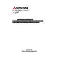
ANODE LEAD REMOVAL
CAUTION: To prevent damage, the following procedure must be used when removing an Anode Lead from the Flyback Transformer.
1) Push the Anode Lead down.
2) While holding the lead down rotate the lead 90º counter clockwise.
3) Carefully remove the Anode Lead from the Flyback Transformer.
CRT REPLACEMENT
1. Removal of the CRT
Caution! High voltage should be completely discharged prior to CRT removal. Since the CRTs receive high voltage from the Flyback transformer, discharge the CRTs by shorting the open end of the respective high voltage cable to chassis ground.
1. Refer to Cabinet Disassembly and remove the Light Box Assembly. 2. Remove the three Anode Lead Wires from the Flyback transformer and discharge the CRTs. (Use the above procedure) 3. Unplug the three PCB-CRTs. 4. Remove 4 screws "a" retaining the Optical Unit. [Figure 1] 5. Remove 4 screws "b" retaining the Lens of the respective CRT 6. Lift the Optical Unit from the Light Box and set it lens down on a flat surface. 7. Remove 4 screws "c" retaining the CRT. [Figure 2] Note: DO NOT loosen the spring loaded screws. Doing so will break the seal between the C-Element and the # 6 Lens, causing leakage of the CRT Coolant. 8. Remove the Deflection Yoke from the neck of the CRT. [Figure 3]
Figure 1 Page 12
|
|
|
> |
|