|
|
|
Categories
|
|
Information
|
|
Featured Product
|
|
|
 |
|
|
There are currently no product reviews.
 ;
I am very happy regarding the online purchase of this manual from Owner-Manuals.com as with this I could set right my Denon CD player and Amplifier.
I once again sincerely thank them for the prompt service which was rendered to me.
N. Shanker
;
More than pleased with my prurchase, very good product for the price.
;
Manual-link came 30 minutes after having paid for an extremely rare (40 years old) item (sony icr-120) and helped me to get the radio rework again. So really good help for me, fast and reliable delivery and -taken that into consideration- a very reasonable price for that service. So thanks again! Mike, Germany
 ;
Some of the pictures in this manual are a bit irritating. I had to dissassemble the unit and some of the screws have different threads, which is not mentioned in this manual. Also some of the drawings of the boards look different than the actual boards.
After all, the manual was very useful. I was able to recalibrate the capstan drive and it is working fine again.
;
This manual is very good. 303 pages scanned in a very high resolution. My camera has bad, leaking capacitors which all of the V5000 models are suffering from these days.
There is a huge part list with all capacitors, transistors etc. in this manual which helped me a lot. Otherwise I would not have been able to buy replacement parts.
The dissassembly guide is very enormous and detailed. Unlike on the Panasonic MS1 manual I downloaded here it actually looks like the real parts look. And the screws are labeled correctly, so you shouldn't have any left after the repair. ;)
X92-4030-0x X92-4440-0x
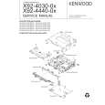
[1] Disc Loading
OPERATION DESCRIPTION
Switch ON! Disc arm(L) Disc arm(R)
(1) Turning the loading switch ON 1) When a disc is inserted, the disc arms open to the left and right and the claw below disc arm (L) sets the loading switch ON. 2) The above starts the motor rotation.
Disc
(2) Loading the disc 1) When the motor starts rotation, the worm gear also starts to turn as shown in the figure. 2) The rotation force is transmitted to the gear train. 3) When the force is transmitted to the final gear, the rollers rotate to pull in the disc.
Worm gear
Motor
Disc guide Disc IN Rubber rollers
Dis
Disc OUT Roller
The disc is pulled in or out when the rollers are pushed against the disc guide.
Side view Disc IN
[2] Operation of Slider (R)
(1) Activating the trigger arm 1) When the disc is pulled in by the rollers, the disc edge pushes the trigger arm and rotates it.
Position pushed by the disc Trigger arm
Center of rotation
2) When the disc is an 8cm disc, it is pulled upwards by the tapering on the disc guide. The trigger arm is rotated when the disc pushes the claw (section A) located before the trigger arm.
Disc Clamper chassis
When the 8cm disc reaches the loading end position, the roller areas supporting the disc decreases. To prevent the disc from dropping in this case, the claw is provided with a projection for supporting the disc.
A
Trigger arm
Claw (A) Projection 8cm Disc Disc
6
|
|
|
> |
|