|
|
|
Categories
|
|
Information
|
|
Featured Product
|
|
|
 |
|
|
There are currently no product reviews.
 ;
The service manuel is very helpful, we where able to restore the device to its working operation again.
;
Great quality complete service manual!!! complete parts list and drawings
;
Again a great job. I never been disilluted from them! Clear scheme, complete and very good for repairing!
;
Great manual just what I needed, great service as always, thanks.
;
Great quality complete service manual! complete parts list and drawings. Thanks!
XAV-7W SECTION 2 GENERAL
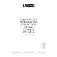
Location of Controls
Main unit
Monitor closed 1 2 6 7
1
This section is extracted from instruction manual.
Card remote commander
The unit can be operated with the card remote commander. For safety, stop the car before using the card remote commander, or have a passenger operate it.
3
2 3 0 qa qs qd 6 7 8 9 qf qg
8 4 0 5
1 DISC �/+ buttons 2 Reset button 3 Sensor for card remote commander 4 VOL (volume adjust) �/+ buttons 5 SEEK/AMS �/+ buttons
4 5
9 qa
6 Display window 7 OFF (Standby/Power off) button* 8 OPEN/CLOSE button 9 ATT button 0 MODE button qa SOURCE (Power on/Radio/CD/MD/VIDEO or TV) button
* Warning when installing in a car without an ACC (accessory) position on the ignition switch After turning off the ignition, be sure to press OFF on the unit for 2 seconds to turn off the clock display. Otherwise, the clock display does not turn off and this causes battery drain.
Monitor opened up
1 DSPL (display mode change) button 2 Number buttons 3 DSO button 4 MENU button 5 SOURCE (Power on/Radio/CD/MD/AUX) button 6 B/b SEEK/AMS �/+ buttons 7 SOUND button 8 OFF (Standby/Power off) button 9 VOL (volume adjust) +/� buttons
0 EQ7 button qa MODE button qs LIST button qd V/v DISC +/� buttons qf ENTER button qg ATT button
Note
If the unit is turned off by pressing OFF for 2 seconds, it cannot be operated with the card remote commander unless SOURCE on the unit is pressed to activate the unit first.
Tip
See �Replacing the lithium battery� for details on how to replace the batteries (page 44).
1 2
1 ANGLE (monitor angle adjust) �/+ buttons
8
2 Sensor for card remote commander
9
Note
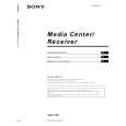
Cluster panel dimensions
175.4
1 Installing the Main Unit
If the installation dimensions shown at right are not observed, the monitor may not open up smoothly. If this happens, check the installation once more and modify the cluster panel where the
(7)
171 (6 3/4)
Installation angle
The unit should be installed within an angle of 25 degrees from horizontal. If this angle is exceeded, the monitor may not open up or retract properly.
Before installation
This unit is designed to be completely safe, but if not installed correctly, it can cause accidents. Be sure to verify the following points before installation. Install the main unit to the in-dash location, and the connection box under the navigator�s seat, etc. � If the monitor in the opened position is close to a airconditioning outlet, the outlet should be closed. � Install the unit so that the monitor when opened up will not block access to the hazard switch or other important controls. � Do not install the unit (monitor) in locations which may be subject to excessively low or high temperatures. (Otherwise the unit may be deformed and the LCD may be damaged.) Exposure to direct sunlight can also lead to high temperatures and should be avoided. Selecting the installation location
dimension requirements are not met. For some car models, a separately available mounting kit may be required. (For details, please consult your dealer.)
25.5
1
(1 /16)
22.5
1 17.3 6.2
( /4)
Center line
33.6
44.7
(1) 25
18
(( /32)/16)
11 29
(22/32) 55.7 (2 1/4)
20.6
(13/16)
(1 3/8)
(1 13/16)
Unit: mm (inch)
Installation procedure precautions
� Perform the installation carefully. Dropping the unit or otherwise subjecting it to strong impact or force may deform the chassis, resulting in failure of the monitor loading mechanism or other defects.
T
TN
N T/N
T
N
T/N T/N
Note
Keep the units and connection cables apart. The Media Center main unit and the connection box 1 should not be in close proximity.
1 2
Set the ignition key to OFF or remove it.
� To allow for proper opening and closing of the monitor, there
Place the units in their intended mounting locations to check the cable length and monitor installation conditions.
must be a clearance of at least 147 mm between the closest position of the gear shift lever and the mounting surface for the unit.
Frequency select switch (E model) The AM (FM) tuning interval is factory-set to the 9 k (50 k) position. If the frequency allocation system of your country is based on 10 kHz (200 kHz) interval, set the switch on the bottom of the unit to the 10 k (200 k) position before making connections.
Gear shift lever
At least 147 mm (5 7/8 in.) from mounting surface
FM 200k FM 50k
AM 10k AM 9k
� In some cases, the gear shift lever may touch the monitor when moved to a certain position. Make sure that there is no obstruction to driving operations. � When installing this unit together with other car audio equipment (single DIN slot size) in a stacked configuration, install the Media Center main unit on top.
5
6
5
 $4.99 XAV-7W SONY
Owner's Manual Complete owner's manual in digital format. The manual will be available for download as PDF file aft…
|
|
|
> |
|