|
|
|
Categories
|
|
Information
|
|
Featured Product
|
|
|
 |
|
|
There are currently no product reviews.
 ;
very good and complete manual , it is in english and german is perfect for repair.
 ;
This manual is complete and of high quality. I am very pleased with the purchase.
;
Another excellent buy! A fully readable PDF archive. Good prints!!
;
It is wonderful done!!! a great job in scanning the manual. Superior quality in all the electric scheme. Very understandable and net!!! Thank you!
;
muy buen manual por lo completo de este algunos esquemas estan muy divididos lo que hace algo dificil el seguimiento.
XC-L5
6.2 TUNER SECTION
6.2.1 FM TUNER SECTION
� Set the mode selector to FM BAND. � Connect the wiring as shown in Fig. 1.
Step No. 1 2 Adjustment Title Front End Sensitivity TUNED IND. Lighting Level FM SG (1kHz, ± 75kHz dev.) Frequency Level (MHz) (dBµV) 98 98 0-30 18 ± 2 Reception Frequency Display 98MHz 98MHz Adjustment Location L6402 T6401 VR6201 Specifications Adjust so that the DC voltage between the IC6201pin 20 and GND becomes at maximum level. Adjust so that the indicator of TUNED IND. starts to light up.
Note: Before adjusting, make sure there is no gap between L6401 and L6402. If there is a gap between them, bring them into contact with each other first, and then make adjustments.
6.2.2 AM TUNER SECTION
� Set the mode selector to AM BAND. � Connect the wiring as shown in Fig. 1.
Step No. 1 Adjustment Title Front End Sensitivity
AM SG (400Hz, 30% Mod.) Frequency Level (kHz) (dBµV/m) 999 (�1) 35-45
Reception Frequency Display 999kHz (�1)
Adjustment Location T6201
Specifications Adjust so that the DC voltage between the IC6201pin 20 and GND becomes at maximum level.
Note (�1): For the area using 10kHz step, frequencies should be 1000kHz.
60cm Loop antenna
AM SG
Center
Center
AM antenna terminal
MPX SG
FM SG FM75� antenna terminal
PRODUCT
DC Voltmeter
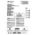
Fig. 1 AM and FM Adjustment Wiring Diagram
FM/AM TUNER MODULE
AM antenna terminal
SIDE A
T6201
YELLOW
BLACK AXX7041 IC6201 Pin 20 T6401 L6401 VR6201
FM antenna terminal
L6402
Fig. 2 Adjustment Point
42
|
|
|
> |
|