|
|
|
Who's Online
There currently are 6003 guests online. |
|
Categories
|
|
Information
|
|
Featured Product
|
|
|
 |
|
|
There are currently no product reviews.
 ;
The service was quick and simple, finding the service manual easy and it appears to be the original with colour schematics. It contained the info I was after and so sorted the problem.
I have copied it to CD and attached the envelope to the inside back cover of the owners manual. Good manual and excelent service. Robin Wood, Wood Electronics, New Zealand.
;
Exactly what was needed to assess the product - excellent value and great service
 ;
Nice to have the service manual for the Sony DCR-TRV345E now. The document is of excellent quality.
;
MACKIE HR824 26 pages English-only Service Manual contains:
1) HR824 technical overview with the description of front and rear panel switches.
2) HR824 specs
3) Block Diagram
4) Wiring Diagram
5) Packaging management
6) Spare part & final assembly list (for PCB rev A and B) + exploded view
7) Test Procedures (where, how to measure voltage...) including Test Point diagram on the PCB.
8) IC and Transistor charts.
Excellent guide: very clear, good scan quality enabling us to print readable diagram :-)
Note:
Mackie HR824 make extensive use of surface mount devices (SMD). Service on the HR824 must
only be undertaken by experienced service technicians with the right tools, experience and patience to perform surface mount rework when needed.
;
This Service manual is very well scanned and its clean to read, no any anti-theft words that un-english could understand. I got my CCD600 working with this manual and it´s clear shematics :)
5
6
7
8
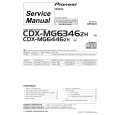
8.1.5 MECHANISM ADJUSTMENT
1 Tangential and Radial Height Coarse Adjustment START
� Remove the 05SD Pickup Assy from the Traverse Mechanism Assy-S. � Remove the joint and the joint spring of the 05SD Pickup Assy.
A
05SD Pickup Assy
Joint
Note: Before removing the flexible cable for the pickup, soldering of the pickup circuit is necessary. For details, see "1 05 LOADER ASSY of 7. DISASSEMBLY".
B
Joint Spring
� Pass through the guide shaft to a new 05SD Pickup Assy. � Attach it to the Traverse Mechanism Assy-S.
05SD Pickup Assy
C
Guide Shaft
� Put the joint between the Tangential (or Radial) adjustment screw and the mechanism base and turn each screw to adjust the height. (Refer to "8.1.1 ADJUSTMENT ITEMS AND LOCATION".)
D
Joint
7.5mm Mechanism base
E
� Attach the Traverse Mechanism Assy-S to the 05 LOADER Assy. � Turn it over and attach the joint and the joint spring. � Arrange the flexible cables. (Refer to "7. DISASSEMBLY".)
F
XC-Z9
5 6 7 8
51
|
|
|
> |
|