|
|
|
Categories
|
|
Information
|
|
Featured Product
|
|
|
 |
|
|
There are currently no product reviews.
 ;
I PURHASED THIS PRODUCT BECAUSE I WAS HAVING PROBLEMS WITH MY CDR20 HARMAN KARDON RECORDER. WHICH I PURCHASED NEW 12 YEARS AGO. AFTER REVIEWING THE MANUAL, I WAS ABLE TO ADJUST THE TENSIONER IN THE SYSTEM. WORKS LIKE A CHAMP!.
SAVED ME AT LEAST 100.00 WHICH WAS WHAT A SERVICE REPAIR STATION WANTED. GREAT MANUAL EASY TO READ. SPECIALLY AFTER I PRINTED THE PAGES WHICH DEALT WITH MY RECORDER. THANKS A LOT!!!!!!!!
 ;
You can fully trust on this one!
All the schematics are very crear an in one piece per page
;
I have never bought a service manual which is as competely readable as this althogh it was a scanned pdf. Thank you for this succesful manual also cheaper than other sites.
;
Thanks for a very good and readable servicemanual. Just what I needed as a "dinosaur technician". I really recommmend this site and will come back.
Åsbjörn
;
The manual I purchased was just what I needed. I was glad to find a site where I can find so many manuals on a wide variety of products.
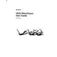
(R2)
Fig-(B)
(R1)
FRAME ASSEMBLY UP/DOWN RUBBER F
Fig-(D) GEAR EMERGENCY (S6) GEAR PULLY GEAR LOADING CAM LOADING (L6) BASE MAIN (R2) (R1)
(S7) (L7) (L6) HOLDER ASSEMBLY DECK ON
(L5) Fig-(C) BELT LOADING MOTOR ASSEMBLY LOADING CONNECTOR(2 PIN) (L5)
(A) Fig-(E) BOTTOM SIDE VIEW Fig-(A)
Fig-11
11. Base Assembly Main (Fig-11)
11-1. Holder Assembly Deck On
1) Push the Locking tabs (L5) at bottom side of the Holder Assembly Deck On in direction of arrow (A) and separate to bottom side. (See Fig-(A))
11-6. Gear Loading 11-7. Gear Emergency
Note: When reassembling, confirm that the Hole (A) of the Cam Loading is aligned to the Hole (B) of the Gear Emergency as Fig-(C). For this alignment, place the Gear Emergency and Cam Loading as Fig-(D), and then move the Gear Emergency in direction of arrow (B) until these two gears are aligned as Fig-(C).
11-2. Frame Assembly Up/Down.
1) Push the two Locking tabs (L6) and lift up the Frame Assembly Up/Down. Note: When reassembling, insert the Lever (R1) of the Frame Assembly Up/Down to the Groove (R2) of the Gear Emergency and lock the two Locking Tabs (L6). (See Fig-(B))
11-8. Cam Loading 11-9. Motor Assembly Loading
1) Release two Screws (S7). 2) Unlock the Locking tab (L7) and separate the Motor Assembly Loading to bottom side. Note: When reassembling, confirm that the Connector (2 Pin) is aligned as Fig-(E)
11-3. Rubber F 11-4. Belt Loading 11-5. Gear Pulley
1) Release the Screw (S6) and lift up the Gear Pulley.
11-10. Base Main
10
|
|
|
> |
|