|
|
|
Categories
|
|
Information
|
|
Featured Product
|
|
|
 |
|
|
There are currently no product reviews.
 ;
Everything okay, thanks a lot. It was a pleasure for me to make a deal with you.
;
A deal without problems, very fast and the manual is a good quality. Sorry for the my english.
;
Superb service and excellent quality of the document received
;
no problems with the purchase of a circuit diagram
;
Scan are good quality and overall just what i was looking for. Thanks!
ELECTRICAL ADJUSTMENT-7/8
2. Servo Adjustment (RF PLL Adjustment)
* * This adjustment can be performed even when the TOP cabinet, operation board or TFT block is removed. To avoid counting track jumps as errors, track jumps are not performed in the test mode and recorded spiral pits are read, unlike during normal DVD playback. Therefore, during service mode startup, only the Aiwa logo appears; the pictures and sound recorded on the disc are not output. During test mode startup, the OPEN/CLOSE detection switch is disabled. During test mode startup, keys other than the POWER key are disabled. The test mode automatically ends after 6 minutes (The disc rotation stops.) To continue the test mode, turn on the power again.
* * *
<XD-DW5 MODEL>
No. 1 2 3 4 5 6 7 8 9 10 Contents Short pin-4 and pin-6 (ground) of CN400 (not mounted). (Preparation for test mode startup) Connect CH1 of the oscilloscope to TP400 (IC400 pin-5) and connect CH2 to TP315 (IC450 pin-60). Insert the test disc (MDVD-191). Turn on the power. (The test mode starts.) Confirm that the pickup reads the outermost circumference of the disc. Rotate VR300 right while checking the waveform of TP315 becomes 4.5±1.0V. Check that the waveform of TP315 is fixed HIGH and the voltage of TP400 is less than 400mV. Turn off the power and turn on again. Confirm that the pickup moves to the innermost circumference. Check that the waveform of TP315 is fixed HIGH and the voltage of TP400 is less than 400mV.
<XD-DW7 MODEL>
No. 1 2 3 4 5 6 Contents Short pin-4 and pin-6 (ground) of CN400 (not mounted). (Preparation for test mode startup) Connect CH1 of the oscilloscope to TP400 (IC400 pin-5) and connect CH2 to TP315 (IC450 pin-60). Insert the test disc (MDVD-191A). Turn on the power. (The test mode starts.) Confirm that the pickup reads the innermost circumference of the disc. Gently rotate VR300 left while checking the waveform of TP400.(The waveform moves rapidly) Then rorate VR300 right gently so that the voltage of TP400 is minimized (less than 400mV). 7 8 9 10 Rotate VR300 left so that the voltage of TP400 is 50mV more than minimum value. Turn off the power and turn on again. Confirm that the pickup moves to the outermost circumference. Check that the waveform of TP315 is fixed HIGH and the voltage of TP400 is less than 400mV.
-76-
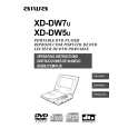 $4.99 XDDW7 AIWA
Owner's Manual Complete owner's manual in digital format. The manual will be available for download as PDF file aft…
|
|
|
> |
|