|
|
|
Categories
|
|
Information
|
|
Featured Product
|
|
|
 |
|
|
There are currently no product reviews.
 ;
Very helpfull information and I highly recommend this source for needed information about your products.
 ;
More than pleased with my prurchase, very good product for the price.
;
This is a good quality scan of the service manual which includes an assembly diagram, block diagram, schematic, and parts list. Exactly what is needed to repair my KR-V55R receiver.
;
Excellent concise manual. All needed information was included. Typeface and diagrams were clear. Very fair price considering what others are charging. Many thanks
;
Response is a little slow- I had to wait 12 hours to receive download link but it says that it may take up to 24hrs.
Manual is old and was not produced in PDF- scanned copy is exellent.
Overall- value for money- I recommend
CHAPTER 6. IPL FROM EP-ROM
Before working on the installation, unplug the AC cord from the AC outlet. 1. Open the top cabinet. 2. Set the IPL switch (S1) to VCC position.
CHAPTER 7. CAUTION TO BE USED WHEN CONNECTING THE RS-232 CABLE
When connecting the RS-232 cable to the XE-A212, be sure to observe the following condiiton: Secure the attached core (RCORF6699BHZZ) to the RS-232 cable in the area within 20mm from the connector. [This is a necessary procedure to support the EMI (Electronics Magnetic Interface).]
IPL switch
S1
GND
IPL ROM 1pin
VCC ROM COPY
3. Install the IPL ROM to the IC socket of the MAIN PWB. 4. Turn the mode key switch to PGM position, and insert AC plug in AC outlet. 5. The IPL procedure is started. When the procedure is completed, the message of �Completed.� Is shown.
RS232 CONNECTOR
Within 20mm Secure the core (RCORF6699BHZZ) to the cable in the area within 20 mm from the connector with a lock band.
P ROM COPY Completed.
6. Unplug the AC cord from the AC outlet. 7. Remove the IPL ROM to the IC socket of the MAIN PWB. 8. Set the IPL switch (S1) to GND position.
S1 GND
VCC ROM COPY
9. Replace the top cabinet. 10. Perform a master reset, insert AC cord in AC outlet.
MRS.
XE-A212V
IPL FROM EP-ROM
� 16 �
 $4.99 XE-A212 SHARP
Parts Catalog Parts Catalog only. It's available in PDF format. Useful, if Your equipment is broken and You need t… 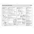 $4.99 XE-A212 SHARP
Quick Start Quick start guide ( sometimes called quick guide ) contains most important information on how to use…
|
|
|
> |
|