|
There are currently no product reviews.
 ;
It's a full manual. All the parts are in there. I haven't found the problem yett, but I am working on it; hope I can rebuild the part myself. To make it more secure and unbreakable this time. Because the part has failed several times before and costs a lot to let it be repaired.
Thanks so much for this rich illustrated and parted manual.
;
I downloaded the document. The manual was complete, well scanned and everything was legible. I could zoom in see what I needed to know. There's not much more that you can ask.
;
It was complete service manual with all needed service informations. Thanks.
 ;
El manual esta muy detallado, los numeros de partes y los esquemas de despiece son correctísimos y muy claros, tanto para los técnicos experimentados como para los novatos.
;
Ottima qualità grafica e completo nelle notizie. Costo abbastanza contenuto.
1
2
3
4
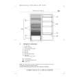
X-HX700
SIDE B
NOTE FOR PCB DIAGRAMS :
A
A TUNER PCB
1. Part numbers in PCB diagrams match those in the schematic diagrams. 2. A comparison between the main parts of PCB and schematic diagrams is shown below.
Symbol In PCB Diagrams Symbol In Schematic Diagrams B CEB CE Part Name
BCE B BCE D DGS GSD GS C EB C E
Transistor
Transistor with resistor
Field effect transistor
Resistor array
3-terminal regulator
Q1 Q4
3. The parts mounted on this PCB include all necessary parts for several destinations. For further information for respective destinations, be sure to check with the schematic diagram. 4. View point of PCB diagrams.
B
Connector
Capacitor
SIDE A
Q2
P.C.Board
Chip Part
SIDE B
Q6 Q5
C
Q9
Q202
D
A
1 2 3 4
23
|