|
|
|
Categories
|
|
Information
|
|
Featured Product
|
|
|
 |
|
|
There are currently no product reviews.
 ;
Some of the pictures in this manual are a bit irritating. I had to dissassemble the unit and some of the screws have different threads, which is not mentioned in this manual. Also some of the drawings of the boards look different than the actual boards.
After all, the manual was very useful. I was able to recalibrate the capstan drive and it is working fine again.
 ;
This manual is very good. 303 pages scanned in a very high resolution. My camera has bad, leaking capacitors which all of the V5000 models are suffering from these days.
There is a huge part list with all capacitors, transistors etc. in this manual which helped me a lot. Otherwise I would not have been able to buy replacement parts.
The dissassembly guide is very enormous and detailed. Unlike on the Panasonic MS1 manual I downloaded here it actually looks like the real parts look. And the screws are labeled correctly, so you shouldn't have any left after the repair. ;)
;
has all the schematics you could need,and very well laid out format also has all part numbers along with an exploded view which is helpful
;
Very nice to have! Now it is no problem to understand how it is put together.
Helps me a lot.
;
good scans, all is clear. all pages in order. recommended
XL-30H/30W
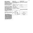
� HF error.
Is output (tracking error signal) obtained at the pins 46 (TEI) and 47 (TEZI) of IC802 the CD TEST MODE "STEP 4" is changed to "STEP 5"? Yes
test mode "step 4" test mode "step 5"
No
Is output obtained at the pins 2 and 5 of BI802/CNS802 No
Optical pickup failure.
Yes Check the periphery of IC801. Check the PWB pattern between pin 12. (TEO) of IC801 and pins 46 and 47 of IC802. Is it normal ? Yes Check the PWB pattern between pin 50 (TEO) of IC802 and pin 18 of IC804. Check the periphery of IC804 and BI801/CNS801. If OK. Optical pickup failure. IC801 is faulty. No
TEI TEZI
Is output (HF signal) obtained at the pin 38 (RFI) of IC802 when the CD TEST MODE "STEP 4" is changed to "STEP 5"? Yes
test mode "step 4" test mode "step 5"
No
Is output obtained at the pins 1 and 3, 4 of BI802/CNS802. No Yes Check the periphery of IC801.
Optical pickup failure.
RFI
Check the PWB pattern between pin 19 (RFGO) of IC801 and pins 38 (RFI) of IC802. If OK. IC801 is faulty
Is output (HF signal) obtained at the pins 41 (RFZI) and 42 (RFRP) of IC802 when the CD TEST MODE "STEP 4" is changed to "STEP 5"? Yes
RFZI RFRP test mode "step 4" test mode "step 5"
No
Check the periphery of IC801. Check the PWB pattern between pin17 (RFRP) of IC801 and pins 41 (RFZI) and 42 (RFRP) of IC802. If OK. IC801 is faulty.
Is the following wave output to the pin 55 (DMO) of IC802 when the CD TEST MODE "STEP 4" or "STEP 5"? Yes
DMO test mode "step 4" test mode "step 5"
No
Check the periphery pins 28~32 of IC802. If OK. IC802 failure.
Normal.
� No sound.
No sound from both L and R-ch? No Yes Check the interval between the pins 82 or 85 of IC802 and the pins 1 or 3 IC601.
Is +4.5V applied to pin 83 (DVDD) of IC802? Yes No
Check the PWB pattern between R819 and Q861.
Is signal of pins 82 and 85 of IC802 output? Yes The main PWB is faulty. No
Check the peripheral parts of IC802. If OK, IC802 is faulty.
� 42 �
 $4.99 XL-30H SHARP
Owner's Manual Complete owner's manual in digital format. The manual will be available for download as PDF file aft…
|
|
|
> |
|