|
|
|
Categories
|
|
Information
|
|
Featured Product
|
|
|
 |
|
|
There are currently no product reviews.
 ;
Very quick response. Very good and accurate print quality of the scanned document.
 ;
The service manual was very usable and clear enough to see the individual values of all of the components (unlike some of the service manuals I have gotten in the past from web sites similar to this one). The price was right and the information was greatly appreciated. It helped me with an otherwise very difficult repair. It was much needed and appreciated. A faster turn around on my order would be nice, but I understand the constraints on your staff's time. Thank you for your service.
;
Excellent manual. Helped me out with disassembling and troubleshooting my projector.
;
thanks you are the best.Very good detail, Quick service response. A useful service manual with all details.
;
Great service!!! Polecam gorąco wszystkim zainteresowanym
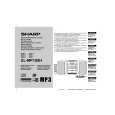
XL-MP100H
KAPITEL 3. BESCHREIBUNG DER MECHANISCHEN BAUTEILE
[1] AUSBAU UND WIEDEREINBAU DER HAUPTKOMPONENTEN
1. BANDMECHANISMUS
Führen Sie zum Ausbau des Bandmechanismus die Schritte 1 bis 5 und 7 des Demontageverfahrens aus. (siehe Seiten 3-3 und 3-4)
(A2)x1 ø2x7mm (A1)x2 ø2x8mm
(A2)x1 ø2x3mm
1.1. Ausbauen der Aufnahme-/Wiedergabe- und Löschköpfe (siehe Abb. 1)
1. Lösen Sie die beiden Schrauben (A1), um den Löschkopf auszubauen. 2. Lösen Sie die beiden Schrauben (A2), um den Aufnahme-/ Wiedergabekopf auszubauen. HINWEIS: Vergessen Sie nicht, nach dem Austausch der Köpfe und der erforderlichen Azimuteinstellung, die Schraubensicherungen anzubringen. Abb. 1
Löschkopf Aufnahme/ Wiedergabekopf
1.2. Andruckrolle ausbauen (siehe Abb. 2)
1. Druckrollensperrklinke vorsichtig in Pfeilrichtung <A> biegen und die Andruckrolle (B1) nach oben herausziehen.
<A>
Andruckrolle (B1)x1 Druckrollensperrklinke
Abb. 2
1.3. Antriebsriemen ausbauen (siehe Abb. 3)
1. Hauptriemen (C1) von der Motorriemenscheibe abnehmen. 2. FF/REW Riemen (C2) von der REW/FF Riemenscheibe abnehmen. 3. Riemen in umgekehrter Reihenfolge wieder einbauen. HINWEIS: Achten Sie beim Einbau der Riemen darauf, dass diese nicht verdreht oder verschmutzt sind.
Hauptriemen (C1)x1
Motor
REW/FFKupplung FF/REW-Riemen (C2)x1
Abb. 3
1.4. Motor ausbauen (siehe Abb. 4)
1. Hauptantriebsriemen entfernen. 2. Die beiden Schrauben (D1) lösen, um die Motorhalterung zu entfernen. 3. Lösen Sie die beiden Schrauben (D2), um den Motor auszubauen. HINWEIS: Achten Sie beim Einbau des Motors auf den korrekten Einbauwinkel.
(D2)x3 (D1)x1 Spezialschraube ø2x4mm Motor Motorhalterung
(D1)x1 ø2x4mm
Abb. 4
Motor
3�1
|
|
|
> |
|