|
|
|
Categories
|
|
Information
|
|
Featured Product
|
|
|
 |
|
|
There are currently no product reviews.
 ;
complete part-lists and pcb layout, schematic diagram is good enlargable,
;
Excellent, fast delivery, excellent product. Good luck!
;
This manual is for the usa model only. But it is clear
, accurate and comprehensive, including board layouts and schematics.
I found it extremely useful for my mitsubishi dp-86da, but the same diagram would also work for the realistic lab5000 and hi fi 80. Thanks.
;
Great to have extra resources for Service Manuals, Now days you can really not trouble shoot efficiently without one , Wayne at IRIONS TV & ELECTRONICS REPAIR Clearwater , Fl. 33755 727-446-7955
 ;
For five bucks you can barely buy a hamburger. Or for the same five bucks you can buy a service manual. Much more useful. (and better for your health, depending on where you buy your hamburgers).
Yes, there are free manual sites out there, but if they don't have what you want, you have to pay.
And five bucks isn't much. Not for full specs, schematics and adjustment and parts replacement procedures.
My only criticism is that grayscale illustrations aren't well rendered, but I've seen worse.
Schematics and text are clear.
I'll be happy to purchase from here again.
Mike
[email protected]
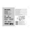
XL-MP110H/MP110E
2. CD MECHANISM SECTION
Perform steps 1 to 3, 14 of the disassembly method to remove the CD mechanism.(see page 3-3,3-4)
Stop Washer (A3) x1 Optical Pickup CD Mechanism (A1) x2 ø2.6 x5mm
2.1. How to remove the Optical Pickup (See Fig. 1)
1. Remove the screws (A1) x 2 pcs and shaft (A2) x 1 pc. 2. Remove the stop washer (A3) x 1 pc and gear (A4) x 1 pc. 3. Remove the optical pickup. NOTE: After pulling out the optical pickup connector, wrap the tip of it with conductive aluminium foil or the like to protect the optical pickup from the static electricity.
Shaft (A2) x1 Gear (A4) x1
2.2. How to remove CD Disc (See Fig. 2~6)
1. When CD is at play position, rotate reduction gear C clock-wise as shown in Figure 2 until disk tray is at �STOCK� position, then rotate the gear further to eject the disk tray (Figure 6) so that CD can be removed from the tray. 2. In another case, if CD mechanism is at tray No. 1 play position and to remove CD located in tray No. 3, the procedure is as follows: If the gear up down board is located at tray No. 1 position, then rotate Reduction gear C clock-wise until Disc tray is at �STOCK� position. Rotate reduction gear D clock-wise (Figure 3) to move the CD mechanism to tray No. 3 position. This is confirmed by checking the gear up down board position base on the marking as indicated on the main chassis as shown in Figure 4. � Usually changer is covered with top plate. As for reference purpose, we exclude the top plate for easy viewing. (Figure 5,6)
Figure 1
Reduction gear C
Front
Rear
Figure 2
Disc Tray Guide Tray CD Disc
Reduction gear D
Up
CD At 'PLAY' position. CD Disc
Down
Figure 3
Gear up down board
CD At 'STOCK' position.
Figure 5
CD Disc
Mark 1 Mark 3 Mark 5 (DISC 1) (DISC 3) (DISC 5) Mark 2 Mark 4 (DISC 2) (DISC 4)
Remove CD from tray. Tray eject
Figure 4 Figure 6
3�2
|
|
|
> |
|