|
|
|
Categories
|
|
Information
|
|
Featured Product
|
|
|
 |
|
|
There are currently no product reviews.
 ;
exactly as they say. Within 24 hours the link to the pages and offcourse it was the right service manual. Super and thanks
 ;
The manual was exact the thing that was promised. My old car stereo is working again thanks to the information supplied.
;
I PURHASED THIS PRODUCT BECAUSE I WAS HAVING PROBLEMS WITH MY CDR20 HARMAN KARDON RECORDER. WHICH I PURCHASED NEW 12 YEARS AGO. AFTER REVIEWING THE MANUAL, I WAS ABLE TO ADJUST THE TENSIONER IN THE SYSTEM. WORKS LIKE A CHAMP!.
SAVED ME AT LEAST 100.00 WHICH WAS WHAT A SERVICE REPAIR STATION WANTED. GREAT MANUAL EASY TO READ. SPECIALLY AFTER I PRINTED THE PAGES WHICH DEALT WITH MY RECORDER. THANKS A LOT!!!!!!!!
;
You can fully trust on this one!
All the schematics are very crear an in one piece per page
;
I have never bought a service manual which is as competely readable as this althogh it was a scanned pdf. Thank you for this succesful manual also cheaper than other sites.
XL-MP150H/MP150E
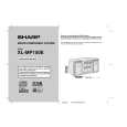
2. CD-MECHANISMUS
Führen Sie zum Ausbau des CD-Mechanismus die Schritte 1 bis 3, 14, 15 des Demontagevorgangs aus (siehe Seiten 3-3, 3-4).
Sicherungsscheibe (A3) x1 Optischer Abnehmer CDMechanismus (A1) x2 ø2.6 x5mm
2.1. Optischen Abnehmer ausbauen (siehe Abb. 1)
1. Die beiden Schrauben (A1) lösen und die Welle (A2) abnehmen. 2. Sicherungsring (A3) und Zahnrad (A4) entfernen. 3. Optischen Abnehmer abnehmen. HINWEIS:U m w ickeln S ie nach d em E ntfernen des A nschlusse s für de n o ptischen A b nehm er da s vo rd ere E nde des A nsch lusses m it leitfähiger A lu m in ium folie, um d en o ptischen A bn ehm er vo r e lektrostatische r A ufladu ng zu schützen.
2.2. CD herausnehmen (siehe Abb. 2~6)
1. Wenn sich die CD in der Wiedergabeposition befindet, drehen Sie das in Abb. 2 dargestellte Untersetzungszahnrad C, bis sich das CD-Fach in der Position �STOCK� befindet. Drehen Sie es dann weiter, um das CD-Fach (Abb. 6) auszufahren, so dass die CD aus dem Fach genommen werden kann. 2. Wenn sich der CD-Mechanismus beispielsweise in der Wiedergabeposition für Fach Nr. 1 befindet und die in Fach Nr. 3 befindliche CD entnommen werden soll, gehen Sie wie folgt vor: Wenn sich die Senk-/Hebeplatte in der Position für Fach Nr. 1 befindet, drehen Sie das Untersetzungszahnrad C im Uhrzeigersinn, bis sich das CD-Fach in der Position �STOCK� befindet. Drehen Sie das Untersetzungszahnrad D im Uhrzeigersinn (Abb. 3), um den CD-Mechanismus in die Position für Fach Nr. 3 zu bewegen. Dies kann anhand der Position der Senk-/Hebeplattebasis zur auf dem Hauptgehäuse gezeigten Markierung überprüft werden (s. Abb. 4). � Der Wechsler ist normalerweise durch die obere Platte abgedeckt. Zur besseren Veranschaulichung ist die obere Platte nicht dargestellt. (Abb. 5, 6)
CD Disc-Fach Führungsfach
Antrieb (A4) x1
Welle (A2) x1
Abb. 1
Untersetzungsrad C
Vorne
Hinten
Abb. 2
Untersetzungsrad D
Auf
Ab
Abb. 3
CD in Position 'PLAY'. CD Disc
Senk-/Hebeplatte
CD in Position 'STOCK'.
Abb. 5
CD
Markierung 1 Markierung 3 Markierung 5 (DISC 1) (DISC 3) (DISC 5) Markierung 2 Markierung 4 (DISC 2) (DISC 4)
CD aus Fach nehmen. Fach öffnen
Abb. 4 Abb. 6
3�2
|
|
|
> |
|