|
|
|
Categories
|
|
Information
|
|
Featured Product
|
|
|
 |
|
|
There are currently no product reviews.
 ;
It was complete service manual with all needed service informations. Thanks.
 ;
El manual esta muy detallado, los numeros de partes y los esquemas de despiece son correctísimos y muy claros, tanto para los técnicos experimentados como para los novatos.
;
Ottima qualità grafica e completo nelle notizie. Costo abbastanza contenuto.
;
Great and quick support. The maual was exactly what I was looking for and my problem
solved. Many thanks.
;
Very good service Within one day i received a pdf of the users manual and electric circuits so I was able to measure the different voltages in the printed circuit and find out the fault Payment was also reliable and easy.Without the manual i could not have repaired.So thanks to "Search for a manual"
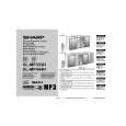
XL-MP333H/XL-MP444H
5. Step 5 Mode When the CD initialization operation flow is completed, the mute is turned off, and playback is started. Even if playback reaches the outermost periphery of disc, the operation does not stop. The LCD display indicates the playback passage time as in case of ordinary CD playback. Turn off POWER to protect the memory of TEST 2 mode. Turn off POWER again to obtain the ordinary operation while the data is stored in the memory (besides TUNER). � The TUNER TEST 2 mode is obtained with >> + MEMORY/SET + ON/STAND-BY. ->Turn off AC in the TEST 2 mode to restore the initial state.
Press the following buttons in this state to obtain the operations specified below. "ON/STAND BY".... "FF/FWD".......................... "REW/REV"........................ Test mode and power turned off to shift to the ordinary standby mode. The pickup slides toward the outer periphery while this button is pressed. The pickup slides toward the inner periphery while this button is pressed. If PICKUP IN is on, input is invalid. Invalid Return to step 1
If AC OFF state is maintained in this state for about 1/2 day, start is executed in the initial state. � To clear the whole memory, insert the AC cord, pressing MEMORY/SET + CD PLAY. 3. Preset frequencies for various destinations (random preset memory) CH 1 2 3 4 5 CH 6 7 8 9 10 CH 16-35 36 37 38 39 40 � BAND BAND FM STEREO FM FM 87.5 MHz FM108.0 MHz FM 98.0 MHz FM 90.0 MHz FM106.0 MHz FM AM 522 kHz AM1620 kHz AM 990 kHz AM 603 kHz AM1404 kHz FM ������ FM106.0 MHz FM 90.0 MHz FM 98.0 MHz FM108.0 MHz FM 87.5 MHz
"PLAY"............................... "STOP"...............................
*If the focus is not received, the process returns to step 1. Other cautions � TOC IL is not available for this test mode.
3. Tuner Test Mode (TEST 2)
1. Outline of tuner (radio) test mode The tuner test mode is intended to store the adjustment and measurement frequencies in the preset memory CH. When adjusting the tuner section in the production line, adjusting personnel are not required to set frequency. 2. Details of tuner test mode Press the "TUNER(BAND)" and "VOLUME UP" buttons in POWER OFF state and turn on the power by the use of "ON/STAND BY" button to preset and store frequency for adjustment and measurement of destination specified by the AREA terminal in the preset memory CH. However, Ordinary 1 and Ordinary 2 are stored in the destinations when the test mode is obtained. (As for frequencies to be preset and stored for each destination, refer to item 3.) The tuner test mode is started from preset No.1. The operations of test mode are identical with the ordinary operations of TUNER function. FUNCTION switching is invalid. It is necessary to discard the content of preset memory when the tuner test mode is ended; be sure to write "0000" or "1111" bits in the memory to be checked for judging memory error at initial setting and to initialize memory. When the tuner test mode is obtained, the following display lights for one second.
AM
BAND
FM MONO
The slant line sections of the table store no memory.
4. Electronic volume Test Mode (TEST 3)
When this test mode is obtained, the following display lights for one second.
In this mode, volume is Volume -14 dB (STEP 23), FLAT AND X-BASS ON, and start-up function to CD, respectively. The button operations in the test mode are the same as those of ordinary operation except volume UP/DOWN. 1) The display is the same as that of ordinary operation except test mode setting. 2) Unlike the ordinary state, the volume is controlled with the volume UP/DOWN button in accordance with the following three steps. Volume- � (STEP 0) <-> Volume-14 dB (STEP 23) <-> Volume-0 (STEP 30) 3) X-BASS is switched when button is pressed.
2�3
|
|
|
> |
|