|
|
|
Categories
|
|
Information
|
|
Featured Product
|
|
|
 |
|
|
There are currently no product reviews.
 ;
I am very pleased with the service manual for my RT-909. This was an easy purchase and great procuct, and much cheaper than other venues i had looked at. This web site is now listed in my favorites list. KEEP UP THE GOOD WORK. THANKS. J. BROWN
;
A very well written and easy to understand manual.
;
There was no problem at all.After paying i had to wait only a few hours,than i could
download the manual in best pdf-quality.
Thank You !
 ;
I found this service manual to be complete in every detail except for troubleshooting charts. It would be helpful if it had a set of troubleshooting charts; however it is a very good manual otherwise and for the price it is very well worth it.
;
Complete manual included schematics layouts and alignment procedure, clear to read and magnify, extremely pleased with manual and owner manual . com's service
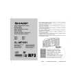
XL-MP45H
SERVICE MANUAL
No. SY379XLMP45H/
MICRO COMPONENT SYSTEM
MODEL
XL-MP45H
XL- MP45H Micro Component System consisting of XL- MP45H (main unit) and CP- XL45H (speaker system).
� In the interests of user-safety the set should be restored to its original condition and only parts identical to those specified should be used.
� Note for users in U.K. Recording and playback of any material may require consent, which SHARP is unable to give. Please refer particularly to the provisions of Copyright Act 1956, the Dramatic and Musical Performers Protection Act 1956, the Performers Protection Acts 1963 and 1972 and to any subsequent statutory enactments and orders. This Service Manual is for the XL-MP45H, which is a minor modification model of the XL-MP35H. This Service Manual, therefore, describes only the changed points from the Service Manual. Please refer to the XL-MP35H Service Manual (SY378XLMP35H/) together with this Service Manual. This speaker CP-XL45H is available in assembles only and may not be disassembled.
CONTENTS
Page
SAFETY PRECAUTION FOR SERVICE MANUAL .......................................................................................................... 2 SPECIFICATIONS ............................................................................................................................................................ 3 NAMES OF PARTS .......................................................................................................................................................... 4 DISASSEMBLY ................................................................................................................................................................. 5 ADJUSTMENT .................................................................................................................................................................. 7 NOTES ON SCHEMATIC DIAGRAM ............................................................................................................................... 8 TYPES OF TRANSISTOR AND LED ................................................................................................................................ 8 WAVEFORMS OF CD CIRCUIT ....................................................................................................................................... 9 BLOCK DIAGRAM .......................................................................................................................................................... 10 SCHEMATIC DIAGRAM ................................................................................................................................................. 15 WIRING SIDE OF P.W.BOARD ...................................................................................................................................... 24 PARTS GUIDE/EXPLODED VIEW
SHARP CORPORATION
�1�
This document has been published to be used for after sales service only. The contents are subject to change without notice.
|
|
|
> |
|