|
There are currently no product reviews.
 ;
Good Quality of the File.
You get the normal manual is incudet.
;
Very nice and real Service Manual, I didn't thought it actually exist in the real world at all.
 ;
VERY NICE FOR COURTESY AND PRECISION!.
tHE SITE IS VERY IMPORTANT FOR ALL DEVICES
vERY GOOD
;
+++ Is is fine, that was what i looking for. Thanks! +++
;
A very good complete archive, i am very satisfied for document.
XL-R5000BK
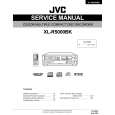
Removing the cams R1/R2 assembly and cam gear L(See Fig.22)
Slit washer 1. Remove the slit washer fixing the cams R1 and R2 assembly. 2. By removing the two pawls S fixing the cam R1, separate R2 from R1. 3. Remove the slit washer fixing the cam gear L. 4. Pull out the cam gear L from the C.G. base assembly. Cam gear L
Slit washer Cam R2
11
Pawl S Pawl S Cam R1
Removing the C.G. base assembly (See Fig.22 and 23)
Remove the three screws 11 retaining the C.G. base assembly. [Caution] To reassemble the cylinder gear, etc.with the cam unit (cam gear and cans R1/R2 assembly), gear unit and drive unit, align the position of the pawl N on the drive unit to that o f the notch on the cam gear L. Then, make sure that the gear unit is engaged by turning the cam gear L (See Fig. 23).
Cam switch board C.G. base assembly
Fig.22
Cam gear L Cam R1, R2 assembly
Notch
Pawl N Cylinder gear
Gear unit
Drive unit
Gear bracket
Fig.23
1-16
|