|
|
|
Categories
|
|
Information
|
|
Featured Product
|
|
|
 |
|
|
There are currently no product reviews.
 ;
Delivery came quite promptly and in a very readable format. Thank you.
;
I found my Clarion VRX8370R in the Camper I bought and I wasn't able for month to understand it.
The Owner Manual was perfect and just what I was searching for.
Thank you.
Leonardo
;
Very good copy of Manual, clear and easy to print off, arrived very promptly and reasonably priced.
Thanks, I will use you again.
;
Zeer duidelijke afdrukken op A4-formaat , zeer uitgebreide handleiding . Pluspunt ,zeer snelle
respons van jullie , binnen de 24h . Top !!!
;
I AM HIGHLY IMPRESSED BY THE EASE OF USE OF THIS DOWNLOAD SERVICE. INSTRUCTIONS ARE CLEAR AND SIMPLE TO FOLLOW....EVEN BY TECHNOPHOBES SUCH AS MYSELF. THE EMAILS POINT YOU IN THE RIGHT DIRECTION...ITS SO EASY PEASY. THE DOWNLOAD CHOICE OF USER MANUALS IS EXTENSIVE AND I COULD NOT FIND A CHEAPER OR MORE EFFICIENT SERVICE ON THE INTERNET. I COULD NOT HAVE MADE A BETTER CHOICE OF INFORMATION PROVIDER. SHOULD I EVER NEED ANOTHER USER MANUAL, THEN THIS IS THE FIRST CHOICE SITE. COULD NOT BE BETTER PLEASED!!!!!!!...MANY THANXES FROM JIM BURNS
To connect digital components
This unit is equipped with two types of digital input/output terminals�coaxial and optical.
When connecting a digital component equipped with a digital input terminal
The following connection allows you to perform digital-todigital recording (from 3-CD Changer onto the other component).
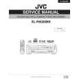
When connecting a digital component equipped with a digital output terminal
The following connection allows you to perform digital-todigital recording on this unit (through the digital terminals).
Before connecting digital optical cable, remove the protective cover from the terminal. Protective plug
COMPU LINK-4 (SYNCHRO)
MODE CDR TD
Audio component with digital output
DIGITAL IN COAXIAL OPTICAL
DIGITAL OUT COAXIAL OPTICAL
To coaxial digital output
To optical digital output
Digital coaxial cable (not supplied)
Digital optical cable (not supplied)
Digital coaxial cable (not supplied)
Digital optical cable (not supplied)
Before connecting digital optical cable, remove the protective cover from the terminal. Protective plug
COMPU LINK-4 (SYNCHRO)
MODE CDR TD
To coaxial digital input
To optical digital input
Audio component with digital input
DIGITAL IN COAXIAL OPTICAL
DIGITAL OUT COAXIAL OPTICAL
When this unit cannot recognize a component connected to the DIGITAL IN COAXIAL or OPTICAL terminal, �UNLOCK� appears on the display. If this happens, press PLAY 3 for 3-CD Changer so that the connected component will be recognized.
� When playing back an MP3 disc, digital signal cannot be output from this unit. Connect also this unit to LINE OUT (PLAY) jacks by using audio cords with RCA pin plugs (supplied). � Digital signal cannot be output through the DIGITAL OUT terminals while recording digitally from an external component.
NOW, you can plug in the unit and other connected components FINALLY!
LINK-4 CHRO)
DIGITAL IN COAXIAL OPTICAL
DIGITAL OUT COAXIAL OPTICAL
To a wall outlet
8
|
|
|
> |
|