|
|
|
Categories
|
|
Information
|
|
Featured Product
|
|
|
 |
|
|
There are currently no product reviews.
 ;
The Service Manual received was helpful. The electronic information is exactly what I needed.
;
The Manual was perfect.
The deliverie was perfect.
Thanks
;
Found website easy to use and manual very clear. First class service
 ;
The quality is quite good and clear. Nothing of the informations inside is lost during the digitalizing process
;
Very good service, fast downloads and good manuals.
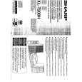
XL-T200H
� HF error.
Is output (tracking error signal) obtained at the pins 31 (TEI) and 32 (TEZI) of IC801 the CD TEST MODE "STEP 4" is changed to "STEP 5"? Yes
test mode "step 4" test mode "step 5"
No
Is output obtained at the pins 3 and 8 of CNP801/CNW801. No Yes Check the periphery of IC802. Check the PWB pattern between pin 11 (TEO) of IC802 and pins 31 and 32 of IC801. Is it normal ? Yes
Optical pickup failure.
IC802 is faulty. No
TEI TEZI
Check the PWB pattern between pin 34 (TRO) of IC801 and pin 25 of IC803. Check the periphery of IC803 and CNP801/CNW801. If OK. Optical pickup failure. Is output (HF signal) obtained at the pin 24 (RFI) of IC801 when the CD TEST MODE "STEP 4" is changed to "STEP 5"? Yes
test mode "step 4" RFI test mode "step 5"
No
Is output obtained at the pins 4 and 5,6 of CNP801/CNW801. No Yes
Optical pickup failure.
Check the periphery of IC802. Check the PWB pattern between pin 19 (RFGO) of IC802 and pins 24 (RFI) of IC801. If OK. IC802 is faulty
Is output (HF signal) obtained at the pins 27 (RFZI) and 28 (RFRP) of IC801 when the CD TEST MODE "STEP 4" is changed to "STEP 5"? Yes
RFZI RFRP test mode "step 4" test mode "step 5"
No
Check the periphery of IC802. Check the PWB pattern between pin17 (RFRP) of IC802 and pins 27 (RFZI) and 28 (RFRP) of IC801. If OK. IC802 is faulty.
Is the following wave output to the pin 41 (DMO) of IC801 when the CD TEST MODE "STEP 4" or "STEP 5"? Yes
DMO test mode "step 4" test mode "step 5"
No
Check the periphery pins 15~19 of IC801. If OK. IC801 failure.
Normal.
� No sound.
No sound from both L and R-ch? No Yes Check the interval between the pins 50 or 53 of IC801 and the pins 1 or 10 of IC601.
Is +3.3V applied to pin 51 (DVDD) of IC801? Yes No
Check the PWB pattern between pin 51 of IC801 and Q803.
Is signal of pins 50 and 53 of IC801 output? Yes The main PWB is faulty. No
Check the peripheral parts of IC801. If OK, IC801 is faulty.
� 33 �
|
|
|
> |
|