|
|
|
Categories
|
|
Information
|
|
Featured Product
|
|
|
 |
|
|
There are currently no product reviews.
 ;
This is a top quality manual. You couldn't get better if you had the original and scanned it yourself. Best price on the net as well. Diagrams are clear and complete, text is sharp and easy to read. Granted you don't get the manual the second you click pay, but the few hours you have to wait for it to be available for download isn't a problem at all. This is a very reliable company.
Very VERY pleased with the product, and will buy others. Thanks!
;
In a word AWESOME.
I never expected the quality and abundant content that I got with this manual. Everything you'd ever want to know from a service perspective is found in this manual, along with... as a bonus, operating instructions on how to use the unit. WOW. Very impressed with the quality of the manual. You won't be disappointed if you're looking for the EVS900 service manual.
;
I thank Owen-Manuals.com for the wonderful service rendered to me, and this manual which I purchased helped me a lot in servicing my Denon System, which was lying in a dead state.
Thanks Owner-Manual.com
;
I purchased this manual to repair my Teac set and with the support of this manual I rectified the problem.
Thanks Owner-Manuals.com
;
Excellent service manual, i didn't believe i could find it for such old product, it is very explanatory, managed to fix the disk player!!!
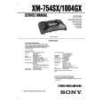
XM-1004GX SECTION 3 ELECTRICAL ADJUSTMENT
Bias Adjustment
Note : The Bias adjustment should be performed only if any of Q108 and Q110 for VR101, Q208 and Q210 for VR201, Q308 and Q310 for VR301, and Q408 and Q410 for VR401 are replaced. Setting :
Stabilized Power supply Digital Voltmeter
Adjustment Location :
� AMP BOARD (COMPONENT SIDE) � VR201 BIAS ADJUSTMENT (FRONT R-CH) VR301 BIAS ADJUSTMENT (REAR L-CH)
B+,REM terminals
set
+ _
VR101 BIAS ADJUSTMENT (FRONT L-CH)
VR401 BIAS ADJUSTMENT (REAR R-CH)
GND terminal
test points
Test Point Location : Procedure: 1. Rotate variable resistors VR101 (FRONT L-CH), VR201 (FRONT R-CH), VR301 (REAR L-CH) and VR401 (REAR RCH) full counterclockwise as seen from the pattern side to minimize the bias current. 2. The input signal is with no signal. 3. Connect the stabilized power supply between B+ and REM terminals and gradually increase the voltage to 14.4 V while checking for any abnormal current. 4. Adjust VR101 (FRONT L-CH), VR201 (FRONT R-CH), VR301 (REAR L-CH) and VR401 (REAR R-CH) so that the digital voltmeter connected between the respective test points reads 4.5±1 mV. RV Ref. No. VR101 VR201 VR301 VR401 Test points TP101 and TP102 TP201 and TP202 TP301 and TP302 TP401 and TP402
� AMP BOARD (CONDUCTOR SIDE) �
TP302 TP301
TP201 TP202
TP402 TP401
TP101 TP102
8
|
|
|
> |
|